Magnetic Circuit Design Guide
1. Basic calculation formulas
1-1. Total magnetic flux Φ and permeance P
The basic calculation formula for magnetic circuits is the same as Ohm's law; namely, when the total magnetic flux is denoted by Φ, the magnetomotive force by F, and the magnetic resistance by R, the relationship among these three elements is expressed by the following formula:
However, in calculating a magnetic circuit, permeance P, which is the reciprocal of magnetic resistance R, is generally used instead of magnetic resistance R. Therefore, the above formula can be replaced by the following formula:
When the magnetic path length is denoted by L, the cross section area of the magnetic path by A, and the permeability of the magnetic path by μ, permeance P is expressed by the following formula:
This formula shows that the shorter the magnetic path length L and the greater the cross section area A and permeability μ, the greater the permeance P ( i.e. the smaller the magnetic resistance).
In addition, permeance Pt for the entire magnetic circuit is expressed by the sum of gap permeance Pg, which is defined as the reciprocal of the magnetic resistance at the gap, and leakage permeance Pf is defined as the reciprocal of the magnetic resistance caused by leakage magnetic flux ( Pt = Pg + Pf ).
To grasp the leakage flux for each magnetic path space, total permeance Pt is expressed as a sum of gap permeance Pg and the leakage permeance of each magnetic path space (Pf1+ Pf2 + Pf3+ ....... Pfn).
1-2. Magnetomotive force loss coefficient f
Magnetomotive force loss coefficient f is defined as the ratio of the total magnetomotive force F of the magnetic circuit to gap magnetomotive force Fg.
The total magnetomotive force F of the magnetic circuit is given by the magnet used, and its value is the product of the magnetic field strength at the
operating point of magnet Hd and magnet length Lm.
In addition, the magnetomotive force of gap Fg is the product of gap magnetic flux density Bg and gap length Lg; therefore, Formula (5) can be expanded to the following formula:
1-3. Leakage coefficient σ
Leakage coefficient is expressed by the ratio of total magnetic flux Φt generated from the magnet in the magnetic circuit to the gap magnetic flux converged in the gap Φg.
Total magnetic flux Φt generated from the magnet is given as the product of the magnetic flux density at operating point Bd and magnet cross section area Am, and the magnetic flux converged in gap Φg is given as the product of gap magnetic flux density Bg and gap cross section area Ag; therefore, Formula (7) can be expanded to the following formula:
In addition, from Formula (2) :Φ = FP, Formula (7) can also be expressed by the following formula:
Because magnetomotive force loss coefficient f generally becomes a value close to 1, Formula (9) will become the following formula by substituting Formula (5) and Formula (4):
This formula can also be expressed in the following form by dividing Pf by each leakage magnetic path space:
1-4. Permeance coefficient Pc
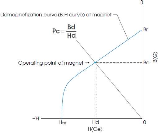
Permeance coefficient Pc is used to express the operating point of the magnet on the B-H curve. This value is defined as the ratio of magnetic flux density Bd and magnetic field strength Hd at the operating point and expressed by the following formula (see the figure above):
1-4-a. Permeance coefficient of the magnet incorporated in a magnetic circuit
The permeance coefficient of a magnet incorporated in a magnetic circuit can be determined by obtaining Hd and Bd from Formula (6) and Formula (8) and substituting them into Formula (11).
And by substituting this to
, the following formula can be obtained:1-4-b. Permeance coefficient of a single body magnet
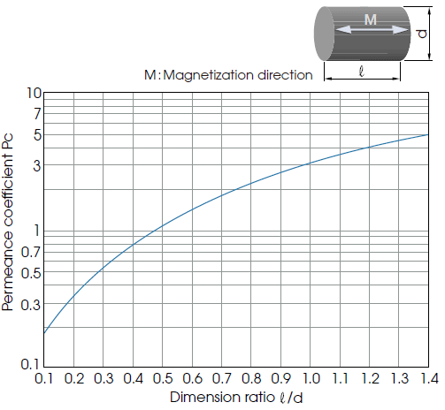
The permeance coefficient of a single body magnet is largely affected by the magnet’s shape, and it is therefore very difficult to obtain an accurate value by calculation.
Therefore, from the figure below using a columnar magnet as a sample (a graph showing the relation between the dimension ratio and permeance coefficient), a rough estimate is obtained.
An approximation formula will be as follows:
1-5. Calculation methods for length Lm, cross section area Am, and volume Vm
Length Lm and cross section area Am required for the magnet are
By giving Hd, Bd, Bg, Ag, Lg, f and σ to this formula, the necessary Lm and Am can be obtained.
And the necessary Vm is
indicating that the necessary magnet volume is in inverse proportion to the energy product at the operating point.
1-6. Method for obtaining leakage coefficient σ and magnetomotive force loss coefficient f
1-6-a. Procedures for experimentally obtaining σ and f
■ Method using a search coil
- 1. Wind a search coil around the magnet and measure the gap magnetic flux.
- 2. Calculate Bd from total flux Φg/magnet cross section area Am.
- 3. Obtain Hd from the B-H curve (demagnetization curve).
- 4. Measure Bg, Ag, Lg, Am, and Lm.
- 5. Calculate f and σ from Formula (6) and Formula (8).
■ Method without using a search coil
- 1. Assume the f value (between 1.0 and 1.2 in general).
- 2. Measure Lm, Bg, and Lg.
- 3. Calculate Hd using Formula (12) on the previous page.
- 4. Obtain Bd from the B-H curve (demagnetization curve).
- 5. Measure Am and Ag, and calculate σ using Formula (8).
1-6-b. Method for obtaining σ by calculation
Obtain Pg and Pf1 through Pfn using formula (10),
and calculate σ.
Reference example
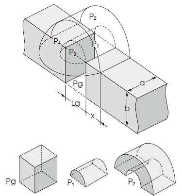
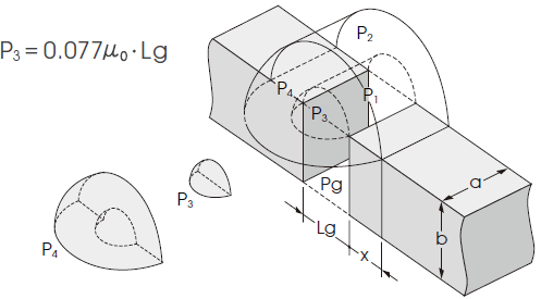
An example of a calculation of permeance of the basic components (Pg, P1, P2 P3, and P4) of the leakage magnetic path space is shown below.
1) Permeance of Gap space area in the figure
2) Permeance of Semicylindrical leakage magnetic path
3) Permeance of Semicylindrical (hollow) leakage magnetic path
4) Permeance of Quarter spherical leakage magnetic path
5) Permeance of Hollow quarter spherical leakage magnetic path
By combining the permeance of the above 1) through 5), a rough estimate of σ in the leakage magnetic path space can be obtained ( μ0 : permeability of vacuum).
2. Calculation formula for the magnetic flux density B(X) on the center line of a magnet
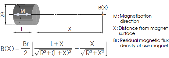
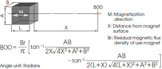
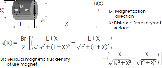
When the B-H curve is straight or operating point Bd is located above the flection point, distribution of the magnetic field outside the magnet can be considered in the same way as that of a magnetic field being generated from a closed circuit current on the outer peripheral surface of a space with a length of X, having the same permeability and cross section shape as the magnet.
The calculation formulas for obtaining this B(X) for three typical shapes will be shown in the following. These formulas are effective as approximation formulas for ferrite magnets or neodymium magnets.
2-1. Cylindrical-shaped magnet
2-2. Square-pillar-shaped magnet
2-3. Tube-shaped magnet
2-4. When a magnetic body is placed behind the magnetic pole
Substitute 2L into term L of Formulas 2-1, 2-2, and 2-3.
2-5. When magnets with the same shape oppose each other at a distance of 2X
B(X) at the gap center will become twice that of the B(X) obtained using Formulas 2-1, 2-2, and 2-3.
B(X) at Point P inside the gap will be the sum of B(X-P), in which X-P is substituted into term X of the previous formula, and B(X+P), in which X+P is inserted into term X of the previous formula.
2-6. When the magnetic body is located behind the magnetic pole in the same configuration as in the previous section
Substitute 2L into term L of Formulas 2-1, 2-2, and 2-3. B(X) at the gap center and Point P inside the gap can be obtained through the same procedures as 2-5.
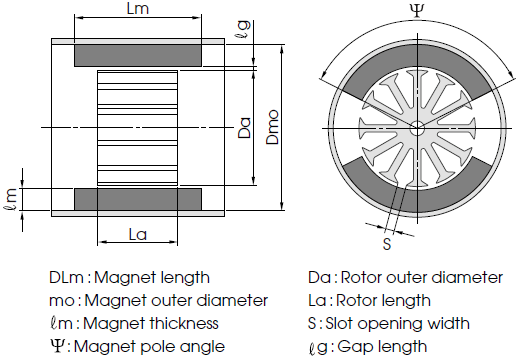
3. Calculation of the effective magnetic flux of magnetic circuits for motors
In magnetic circuits for motors, the magnetic circuit conditions vary widely depending on elements including the number of rotor slots, the slot shape, and the case wall thickness. Therefore, in this section, only formulas that show basic concepts will be shown.
1) Magnet cross section area Am
2) Equivalent size ratio of a magnet ℓ/d
3) Leakage permeance coefficient of a single body magnet Pi
4) Permeance coefficient of a single body magnet including the yoke PL
5) Curter’s coefficient Kc
6) Effective permeance coefficient Pu
7) Leakage magnetic flux σ
8) Magnetic flux of the poles (or Effective magnetic flux) Φg
About saturation of a magnetic circuit
The above Φg calculation method does not take
into consideration the saturation of the magnetic circuit. However, in actual magnetic circuits, saturation may occur in the case or rotor area.
In other words, when Φg obtained by the above calculation method and Φg in the actual motor are compared and g in the actual motor is smaller than the calculated value, it is possible that the magnetic circuit is saturated.
SI/CGS units conversion table
By multiplying the characteristic value in the SI unit by the conversion ratio on the left side of ▶, the value in the CGS unit can be obtained.
Similarly, by multiplying the characteristic value in the CGS unit by the conversion ratio on the right side of ◀, the value in the SI unit can be obtained.
| SI unit▶ | ◀CGS unit | ||||||
|---|---|---|---|---|---|---|---|
| Magnetic term | Item symbol | Unit name | Unit symbol | Conversion ratio▶ | ◀Conversion ratio | Unit symbol | Unit name |
| Magnetic flux | Φ | Weber | Wb | 108▶ | ◀10-8 | Mx | Maxwell |
| Magnetic flux density | B | Tesla | T | 104▶ | ◀10-4 | G | Gauss |
| Magnetic field | H | Ampere/m | A/m | 4π×10-3▶ | ◀103/4π | Oe | Oersted |
| Magnetization | M | Ampere/m | A/m | 10-3▶ | ◀103 | G | Gauss |
| Magnetic polarization | J | Tesla | T | 104/4π▶ | ◀4π×10-4 | G | Gauss |
| Magnetomotive force | Fm | Ampere | A | 4π×10-1▶ | ◀10/4π | Gi | Gilbert |
| Magnetic attraction force | F | Newton | N | 105▶ | ◀10-5 | dyn | Dyne |
| Permeability | μ | Henry/m | H/m | 107/4π▶ | ◀4π×10-7 | Dimensionless | |
| Permeability of vacuum | μ0 | 4π×10-7Henry/m | H/m | Dimensionless | 1 | ||
| Magnetic resistance | Rm | 1/Henry | H-1 | 4π×10-9▶ | ◀109/4π | Gi/Mx | Gilbert/Maxwell |
| Permeance | P | Henry | H | 109/4π▶ | ◀4π×10-9 | Mx/Gi | Maxwell/Gilbert |
| Magnetic energy product | BH | Joule/m3 | J/m3 | 4π×10▶ | ◀10-1/4π | G · Oe | Gauss · ersted |
| 10▶ | 10-1 | erg/cm3 | Erg/cm3 | ||||


