Stray-field compensation
by TMR sensor
Degradation of accuracy due to stray-field noise is a common problem for magnetic field sensors. Securing a distance between the source of stray field and the sensor, or placing a magnetic shield, are major restrictions on design and lead to higher system costs. In addition, it was difficult to select an appropriate design while adjusting the balance between compensation effectiveness and cost. As a solution, TDK proposes a method of suppressing magnetic stray-fields using multiple sensors. In the "summary of compensation measures" below, the effect of stray field is compensated by using the output difference of two sensors that output opposite phases to the magnetic field signal. By selecting the number of sensors to be used, rational countermeasures can be selected while considering the expected stray field and allowable angular error.
Overview of On-Axis Countermeasures
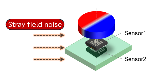
- Sensor 1 and sensor 2 are placed on both sides of the board coaxial with the rotating magnet. In this case, the output of the two sensors are almost in phase and at the same level for the stray-field (magnetic field) noise.
- The correction effect is enhanced by adjusting the thickness of the substrate so that the magnetic field strength received by sensor 1 and sensor 2 is a certain ratio of B1/B2>1.5 among the two sensors on the coaxial axis. (Gradiometer design)
- ・The same vector and the same magnetic field strength are included from the disturbing magnetic field(stray-field), resulting in a difference in the output angle of each synthetic vector of sensor 1 and sensor 2. This is because the magnetic field strength received from the target magnet is different, resulting in a difference in the synthesis vector of the two sensors.
- * The stray-field noise can be eliminated by offsetting The difference in magnetic field strength from The target magnet of both sensors and The difference in The synthesis vector of The two sensors changed by The stray-field.
- The compensation of the stray-field can be done with each sample of a sensor signal which allows high dynamic stray-field compensated operation and compensation of DC and AC fields.
How to calculate On-Axis
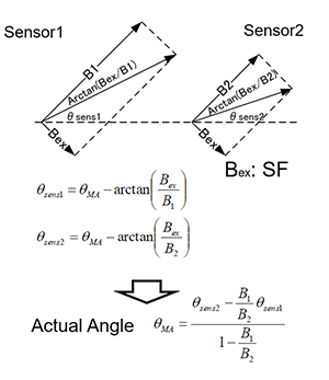
B1, B2 : Sensors 1 and 2 receive "Target Magnet Strength" (Could be any known magnetic field strength but ration is the key)
Bex : Extra magnetic field coming from the outside (stray-field) If there is this, the output of the sensor will be shifted.
θsens1, θsens2 : The angle actually measured by sensors 1 and 2 (slightly offset by the stray-field)
θMA : Angle of the target magnet
θMA = (θsens2 − (B1/B2)·θsens1) / (1 − B1/B2)
This formula estimates the true angle by assigning greater weight to the measurement from the sensor (Sensor1) experiencing the stronger magnetic field from the target magnet, thereby counteracting the effects of external interference.
- Comparison of the Effects of Stray-field compensation
| Number of sensor | Sensor 1 | Sensor 1 Sensor 2 (After Stray-field compensation processing) |
|---|---|---|
| Impact of stray field noise on Angle error | ±2.87° | ±0.17° |
If there is one sensor, the angular error is large, but by using two, the error is reduced
*Under our simulation conditions (Target magnet Br=330mT(Axial magnetisation, single-pole pair cylindrical magnetΦ15.0*t2.0mm), Stray-field=4kA/m (equivalent to magnetic flux of 5mT), B1=100mT, B2=45mT, Gap between Sensor1-Magnet surface=1.0mm, B1/B2 ratio=2.2)
By using two TMR sensors with a constant B1/B2 ratio, external magnetic fields can be compensated.
By ensuring that B1/B2 > 1.5, the compensation effect is enhanced.
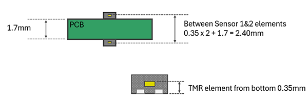
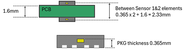
- Examples in board thickness
・DFN4 package (TAS2240)
・DFN8 package (TAS2142)
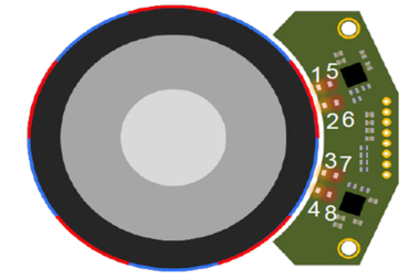
Overview of Off-Axis
Countermeasures

・Place two sensors at positions 1 and 2 that output 180 degrees out of phase with respect to the magnetic field signal from the magnet. At this time, the two sensor outputs with respect to stray field are substantially in phase and at the same level.
・Using a differential output increases the signal power and suppresses the influence of stray-field noise.
Comparison of effects by number of sensors
| Sensor | Sensor1 (Single) |
Sensor1 (2 sensor)
Sensor3 | Sensor1 (4 sensor)Sensor2 Sensor3 Sensor4 |
Sensor1 (8 sensor)Sensor2 Sensor3 Sensor4 Sensor5 Sensor6 Sensor7 Sensor8 |
|---|---|---|---|---|
| Angle error caused by magnetic stray fields |
±1.5゜ | ±0.5゜ | ±0.35゜ | ±0.15゜ |
The number of sensors used and their arrangement can be adjusted according to the target accuracy and the cause of the angular error to be improved.
*Under our simulation conditions (magnet Br: 270 mT, stray-field strength: 5 mT)
How to calculate Off-Axis
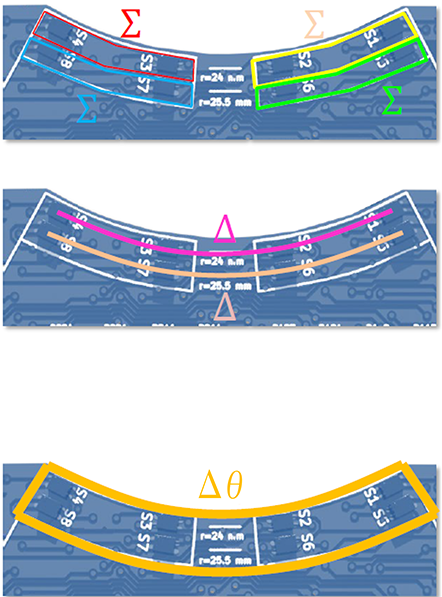
- Step 1: Add sin and cos outputs of two adjacent sensors
*S12 = S1 + S2, also S34, S56, S78
--> Suppresses the distortion of the second harmonic component that occurs in off-axis angle detection - Step 2: Find the difference between the sum of two adjacent sensor outputs found in step 1
*S34 – S12 = S1234, S78 – S56 = S5678
--> Increase resistance to stray field - Step 3: Calculate arc tan from S1234 and S5678
*Angle θ1234 obtained from the inner sensor
*Angle θ5678 obtained from the outer sensor - Step 4: Compare the detected angle values of the inner and outer sensors
*The magnetic field strength of the outer sensor is half that of the inner sensor
*θ1234 has twice the accuracy of θ5678 against stray field
*So 2 x θ1234 – θ5678 = θ12345678
--> It is possible to further increase the stray-field resistance
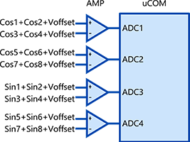
Block diagram with 8 sensors
Related information
YouTube
For questions, requests for samples/evaluation boards, etc., please contact us from here.

For inquiries related to our products or sales, please contact us by filling the following Contact Form.
Contact FormPlease click here for information on the list of distributors.

