ACT1210D Common-mode Chokes for CAN FD

Contents
CAN BUS Communication Circuit and Transmission Waveform
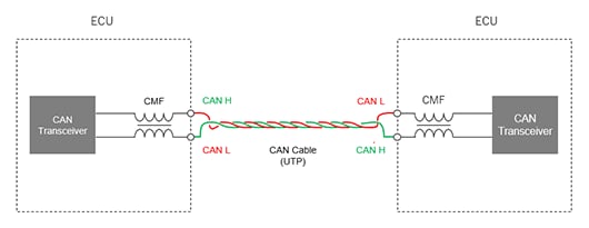
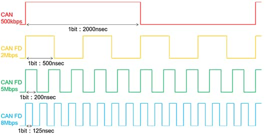
CAN generally supports communication speeds of 500 kbps, but a communication protocol called CAM FD (CAN with flexible data rate) has been standardized and is now being installed in vehicles to enable high-speed communications of larger capacity of data.(Figure1,Figure2) Three communication speeds have been specified for CAN FD: 2 Mbps, 5 Mbps, and 8 Mbps.(Table1)
| Item | CAN | CAN FD |
|---|---|---|
| Communications speed | 500 kbps | 2,5,8Mbps |
| Communications line | Twisted pair cable | |
| Types of electrical signal | Differential voltage | |
| Data length | 1 to 8 bytes (variable) | 1 to 8, 12, 16, 20, 24, 32, 48, or 64 bytes (variable) |
CAN/CAN FD Network Structure
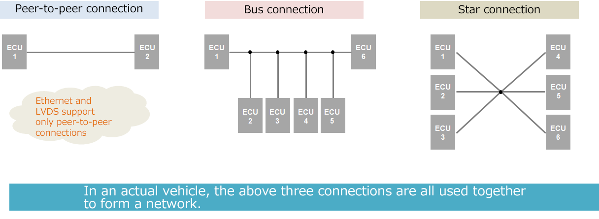
The CAN (CAN FD) communications system is characterized by an ability to connect multiple devices on a single bus line and for those devices to exchange data with one another. (Figure 3) Ethernet and LVDS, such as 100 BASE-T1 and 1000 BASE-T-1, which have been installed in many vehicles in recent years, require a one-to-one communication, but CAN allows a one-to-in connection, and an ECU can be added. Another advantage is that it has a large degree of freedom, such as minimizing the need to review wiring when system changes occur.
CAN/CAN FD networks allow multiple devices (ECUs) to be connected on the same bus.
Ringing
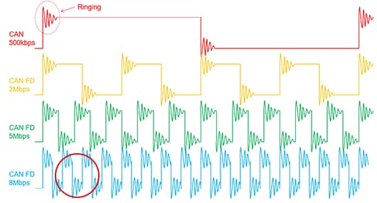
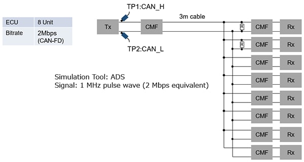
Due to the large degree of freedom of the CAN (CAN FD) communication system, there are many reflection points on the bus and the capacitance component of the hanging ECU is large, making it easy for communication signals to cause ringing. Figure 4 shows a comparison of one-bit times with 500 kbps CAN and 2 Mbps, 5 Mbps, and 8 Mbps CAN FD. Figure 5 is an image of the ringing waveform when a signal is transmitted using a communication circuit structure that causes ringing. The same ringing is observed in the rise and fall portions of the 1-bit time.
In areas where the communication speed is slow, the ringing time is short as a ratio because the time for one bit is long and the time after ringing converges is long, so it is believed that HI and LO can be determined stably, but in the fast communication speed range, the signal shifts from HI to LO before the ringing converges, and this ringing affects the HI/LO determination, increasing the likelihood of a communications error.
Causes of Ringing Occurrence
It is believed that the following are causes of the occurrence of ringing.
(1)Reflection in the junction points of the CAN harness (topology design)
(2)Overall inductance and stray capacitance including from the ECU to the wiring harness (harness length, PCB pattern design)
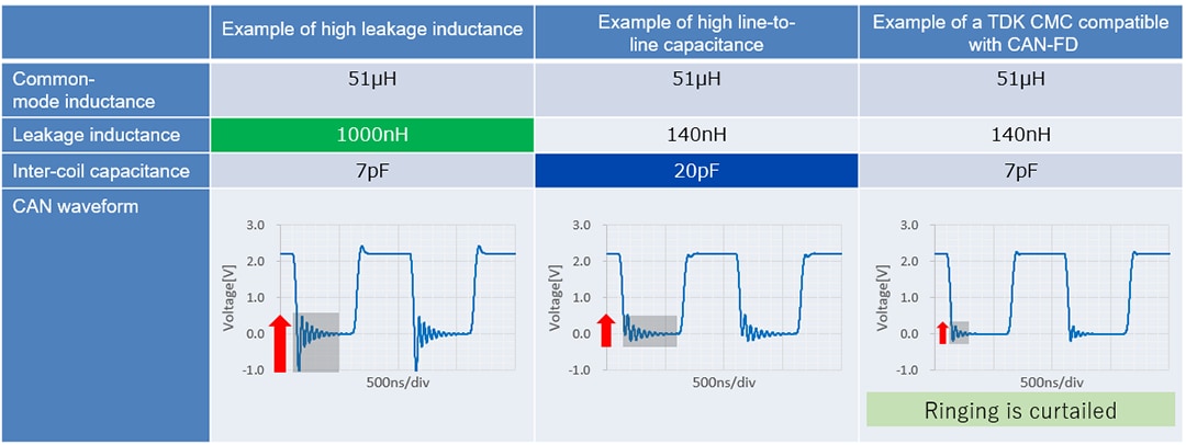
Table 2 is an example of the results of a simulation using TDK’s simulator of the ringing waveform when the leakage inductance and interline capacitance of the common-mode choke are intentionally increased.
From these results, we can see that leakage inductance and line-to-line capacitance have an effect on ringing. For this reason, the characteristic required of common-mode chokes mounted on PCBs for EMC countermeasures of ECUs is minimizing the leakage inductance and stray capacitance between lines as much as possible.
Optimal Common-mode Chokes for CAN FD
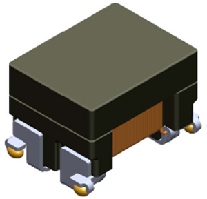
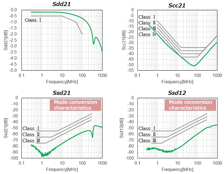
To avoid this type of problem, various characteristics standards for common-mode chokes are being established by organizations such as the IEC, and TDK created ACT1210D type common-mode chokes for CAN FD that satisfy these characteristic requirements.
■ ACT1210D type
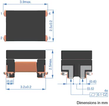
■ Shape and dimensions
■ Product characteristics
- Compatible with 3225 size
- Original structure design achieves the industry's highest level mode conversion characteristics (Ssd21)
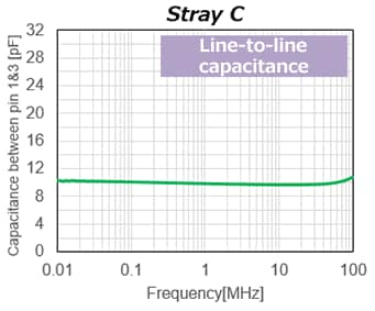
- Achieves good stray C compatible with CAN FD
- High reliability is insured by metal electrodes and a wire connection method that uses laser beam welding; supports an operating temperature range of -40°C to +150°C
- Provides reliability compliant with AEC-Q200
- Stable mass production is possible using original automated winding technology
■ Characteristics and standards
| Common-mode inductance [100kHz] (μH) |
Permissible range | DC resistance -40 to +125°C (Ω)max. |
Insulation resistance (MΩ)min. |
Rated current (mA)max. |
Rated voltage (V)max. |
Product No. |
|---|---|---|---|---|---|---|
| 100 | +50/-30% | 3 | 10 | 115 | 80 | ACT1210D-101-2P-TL00 |
| 51Under development | +50/-30% | TBD | TBD | TBD | TBD | ACT1210D-510-2P-TL00 |
Comparison of Radiated EMI Data and Differential Signal Waveforms with the ACT1210 Series of CMC Compatible with CAN FD
In this section we will introduce an example of an evaluation using the CISPR25 ALSE method with ACT1210D-510 (under development) and our experimental board equipped with a CAN FD compatible CAN transceiver.
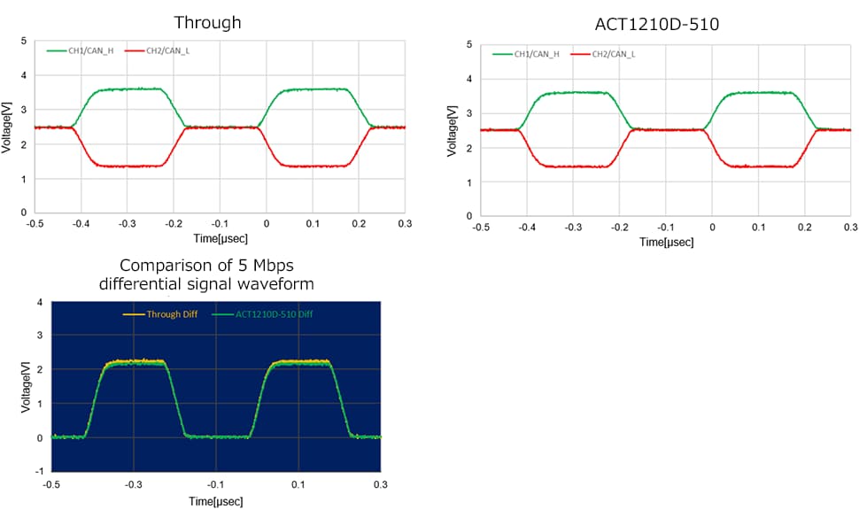
The communications speed is 5 Mbps and the effect of the common-mode choke is confirmed. Figures 9 and 10 show the results of waveform evaluations in a system where radiated EMI evaluation was performed.
The ACT1210D-510 (under development) is mounted on both the TX and RX sides, and the differential signals of CAN H and CAN L of the RX side transceiver can be observed. The calculated differential signals are displayed. There are no differences in the rise and fall waveforms when compared with no common-mode choke (Through). (Figure 11)
Summary
The ACT1210D type is optimized for CAN FD applications that are more susceptible to ringing by minimizing leakage inductance, stray capacitance, and mode conversion characteristics through unique structural design including the winding method. TDK will continue to respond to customer requirements by providing comprehensive product services for common-mode chokes for automotive communications.

