Product OverviewChip Antenna ANT Series
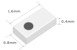
TDK's ANT series ceramic chip antennas feature compact and low profile designs utilizing low temperature co-fired ceramic technology (LTCC). Even with their small size and thin profile, TDK antennas maintain high performance and reliability, all with the industry's smallest "keep-out" area on the PCB which enable ease of PCB design and revision at each development stage.This Tech Note will offer some valuable information to assist you on designing your product with TDK's ANT series chip antenna.
Contents
- Product Feature 1: Compact sizes
- Product Feature 2: High performance even at positions other than PCB corners
- Product Feature 3: Multi-band antenna lineup
- Product Feature 4: Board revisions at each development stage are unnecessary
- Product Feature 5: Simple product design compatible with automatic mounting and reflow
- Contact
- Related Links
Product Feature 1: Compact sizes
Antenna size
Antenna area size
Figure 1 shows the results of simulations performed on a circuit board using 3 different types of antennas.
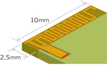
Compared to PCB pattern antennas and mechanical antennas, TDK's chip antennas can successfully reduce antenna area sizes with no degradation of performance.
| TDK chip antenna | PCB pattern antenna | Mechanical antenna | |
|---|---|---|---|
| Whole PCB view | |||
| Details | |||
| Comparison of antenna performance | |||
Product Feature 2: High performance even at positions other than PCB corners
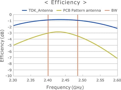
TDK offer antennas suitable for a variety of mounting position on the PCB allowing for greater design flexibility. In certain antenna mounting position where PCB Pattern antenna do not performance so well, chip antenna can provide excellent performance in comparison, as shown in Figure 2. In the simulation below, TDK's antenna are shown to have better performance by 2dB or greater, even with less than half the antenna area as PCB pattern antenna.
Product Feature 3: Multi-band antenna lineup
TDK's chip antennas are available as multi-band antennas.
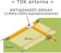
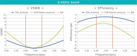
Figure 3 shows the modification of a 2.4GHz-band PCB pattern antenna into a 2.4/5GHz dual-band antenna using a chip antenna from TDK.
In this example, the antenna area is reduced and it is successfully changed to a dual-band type with no degradation of its 2.4GHz-band performance.
Product Feature 4: Board revisions at each development stage are unnecessary
TDK's chip antenna performance can be optimized using capacitor and/or inductor as tuning elements. This flexible design aspect allow for easy fine-tuning at each stage of design without changing the PCB layout.
TDK offers simplified antenna simulation tool to help you gauge the antenna performance by changing antenna mounting positions and keep out area size to determine feasibility study for your application.
| TDK chip Antenna | PCB pattern antenna | |
|---|---|---|
| Additional costs associated with changes in mounting positions or surrounding metallic materials | TDK's chip antenna can be tuned with capacitors and inductors. Since the values for these elements can be changed at each development stage, there is no need to revise the board layout. |
The resonant frequency of the antenna will be slightly affected by factors such as the surrounding metallic materials. Therefore, if PCB pattern antennas are used, it will be necessary for the layout to be revised at each customer development stage. |
Product Feature 5: Simple product design compatible with automatic mounting and reflow
As shown in figure 4, TDK chip antenna are SMD components so they do not have additional cost associated with other types of antenna design since they can be mounted by reflow process.


