Wireless Power Transfer Products
Table of Contents
- Systems and standards of wireless power transfer products
- Merit and demerit of electromagnetic induction and magnetic resonance systems
- Impacting factors of transmission efficiency of electromagnetic induction-based wireless power transfer
- TDK's wireless power transfer coil boasts the latest magnetic technologies
- Material and thickness of magnetic sheet demand careful designing
- Technologies required for wireless power transfer of wearable devices and hearing aids, etc.
- Features of TDK's small, low-output wireless power transfer system
Systems and standards of wireless power transfer products
One of the most rapidly spreading technologies involves wireless power transfer (also called non-contact feeder, non-contact power transmission) systems, capable of charging a built-in rechargeable battery of an electronic device.
TDK offers a diverse, wide range of wireless power transfer products to support different applications: low-output/medium-output for smartphones and laptops, higher output wireless feeding for industrial equipment and EVs (electric vehicles), and ultra-compact, thin-profile systems for wearable and/or health-care devices.
Among all different schemes available for wireless power transfer, current mainstream systems are electromagnetic induction system and magnetic resonance system which utilize magnetic field coupling for power transfer (Figure 1).
Main standards available for wireless power transfer include Qi standards set by an industry standardization body Wireless Power Consortium (WPC), and AirFuel by the AirFuel Alliance (founded through the merger of A4WP and PMA in 2015).
TDK, a participating company in both WPC and the AirFuel Alliance, has been leading the advancement of R&Ds necessary in developing wireless power transfer technologies such as electromagnetic induction and magnetic resonance systems, from early stages. It has commercialized products to meet various specifications, including coils for wireless power transfer.
In the following section, we will introduce TDK's newly-developed wireless power transfer system, which boasts both the position-free capacity with no accurate positioning required and the simultaneous multi-device charging of small electronics, based on an electromagnetic induction system, and wireless power transfer principles and relevant element technologies of electromagnetic induction.
Merit and demerit of electromagnetic induction and magnetic resonance systems
Electromagnetic induction and magnetic resonance systems realize contactless power transfer by using power-receiving coil unit to capture magnetic field generated at the power transmission coil. Many charging pads on the market that enable smartphones to charge when simply being placed on the pad are based on wireless power transfer from electromagnetic induction system (Qi-compliant standard for low-power device, etc.). Electromagnetic induction wireless power transfer is a technology which has been widely used in electric shavers and cordless phones. While its strengths are simple principle and structure, and low-cost system manufacturability, it is also prone to a drastic drop in power transmission efficiency when the distance between the power transmission and receiving coils become larger, resulting in the restriction to maintain the coils in a close range.
In contrast, magnetic resonance-based wireless power transfer transmits power as the system inserts a capacitor in power transmission and receiving sides to form LC resonance circuits, and tunes both sides to resonate at the same resonance frequency. This gives the system an ability to maintain power feed even with a larger inter-coil distance, and/or when the centers of the coils are slightly shifted. This system realizes a charging pad which can recharge multiple portable devices simultaneously.
The inserted Figure 2 summarizes basic circuits and features of both systems (electromagnetic induction and magnetic resonance).
| Electromagnetic induction | Magnetic resonance | |
|---|---|---|
| Power transmission range | 10 mm or less(*) | 50mm or less(*) |
| Difficulty of system configuration | Relatively easy | Relatively difficult |
| System cost | Relatively low | High (projected) |
| Product size | Size reduction feasible | Size reduction difficult |
| Number of devices for simultaneous charging | One on one | Multiple-device capable |
The fact that magnetic resonance system can provide larger power transmission range, as well as EV battery charging while in motion, put this wireless power transfer technology quickly in the spotlight in recent years. Yet, as magnetic resonance system's complexity makes it difficult to reduce device size, electromagnetic induction system will remain as the prominent wireless power charging option for small electronic devices such as wearable terminals and hearing aids. For this reason, we will explain further the wireless power transfer principle and technology of electromagnetic induction system.
Impacting factors of transmission efficiency of electromagnetic induction-based wireless power transfer
The reason why coils must be placed in close range during wireless power transfer using electromagnetic induction is because magnetic inter-coil coupling weakens with transmission failure due to leakage flux starting to generate in part of magnetic flux, as the two coils become further away from each other (Figure 3).
In the case where an inductance of transmission coil and receiving coil is set as L1 and L2 respectively, and a mutual inductance between the coils as M, the degree of magnetic coupling in a coupling coefficient k can be expressed by the following formula:
k=M/√L1・L2
The relationship of L1·L2 ≧ M seen in inductance values of the two coils and their mutual inductance, produces a range of 0≦k≦1 for the coupling coefficient. Although an ideal value of coupling coefficient without no leakage flux is 1, the figure produced in reality is less than 1, and it declines ultimately to 0 as the leakage flux increases with widening inter-coil distance.
Our main target on electromagnetic induction-based wireless power transfer therefore focuses on minimizing the loss even with a coupling coefficient of less than 1, to attain better power transfer efficiency.
For transmission and receiving coils, main impacting factors of lower power transmission efficiency are loss of copper and iron.
| Copper Loss | Copper loss is a loss generated by electric currents in the conductors of coil. Loss will decline as the value of DC resistance becomes smaller. However, electromagnetic induction wireless power transfer system utilizes high frequency AC current. AC current starts to flow in the surface of conductive wire, not inside it, as frequency gets higher (skin effect) resulting in smaller effective cross-sectional area to increase electric resistance. The transmission and receiving coils are designed with litz wire composed of bundled, many twisted small wires with insulation coating, to reduce loss from this skin effect. |
|---|---|
| Iron Loss | Iron loss primarily describes the loss generated at the core of transformer (magnetic core) where magnetic lines generated by coil converge, and includes eddy current loss and hysteresis loss. wireless power transfer also utilizes magnetic sheet equivalent with the transformer core, in its transmission and receiving coils. As described later, its characteristics deeply affect the power transmission efficiency. |
TDK's wireless power transfer coil boasts the latest magnetic technologies
Higher electric transmission efficiencies attainable at higher frequencies (generally in the range of 100 to 200 kHz) is the reason why electromagnetic induction wireless power transfer system for smartphones etc. utilizes this frequency band. However, not only power transmission efficiency is influenced from the distance between the coils, it declines even with a slight shift in position from the core center. This makes accurate positioning of the transmission and receiving coils extremely important.
With the aim to realize such accurate positioning, the Qi standard for WPC's low-power (max. 5 W) devices (Volume I Low Power) defines specifications pertaining to the following three methods, as examples.
| (1) Magnet alignment method | It utilizes attraction of magnet for positioning. |
|---|---|
| (2) Moving coil method | It detects a device to be charged, and moves its transmission and receiving coils to the location of the detected device with a certain type of driving mechanism. |
| (3) Coil array method | It aligns a large number of transmission coils, to actuate ones located right below a device being placed. |
Among these three methods, (1) magnet alignment method is the most simple. As this method uses attraction of magnets placed at the center of transmission coil to draw a magnetic body placed in the center of the receiving coil for positioning, there are some areas that require consideration when designing magnetic circuits as described later.
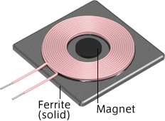
Moreover, receiving coils must operate normally under all three methods above to receive Qi standard certification. For this reason, TDK first designed Tx (transmission) coil unit and Rx (receiving) coil unit which are compliant with the magnet alignment method, and commercialized them. This design then was used to base products that operate using moving coil and coil array methods for product development on. TDK's WPC-compliant Tx coil unit (example) is shown in Figure 4.
Dimension and WPC specification:
Φ50mm(A10)
Dimension and WPC specification:
52×52mm(A1, A9)
Dimension and WPC specification:
100×56mm(A6)
Material and thickness of magnetic sheet demand careful designing
For the applications in portable devices such as smartphones with wireless power transfer capability, receiving coil and magnetic sheet to incorporate must be as thin as possible. However, careful designing is also required on characteristics and thickness of magnetic material. This is due to an issue of magnetic saturation that presents itself when magnetic sheet becomes too thin. Magnetic saturation may cause a sudden drop in coil inductance, resulting in wireless power charging failure.
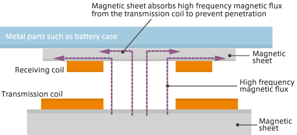
Depending on the location of receiving coil installation, abnormal heat may also become generated. For example, in a case where a receiving coil is placed in close contact with a battery, without a magnetic sheet with adequate magnetic shield property, high frequency magnetic flux will reach the battery case passing through the sheet. As battery cases are generally made of aluminum, high frequency magnetic flux generates eddy-current over the case, causing not only a decline in power transmission efficiency due to iron loss, but also a risk of abnormal heating. An unfailing, safe magnetic shield is required especially on the receiving coil side under the magnet alignment method. This is for additional magnetic flux from the magnets, along with high frequency magnetic flux being transmitted from the transmission coil, which must be absorbed and shielded from.
Soft magnetic material used in magnetic sheet greatly affects the magnetic shield property. TDK has adopted, for its power transfer devices, high performance ferrite for high frequency and soft magnetic material which are used in the core of transformers and choke coils, to magnetic sheets for its transmission and receiving coil units. This works to efficiently focus magnetic lines for better power transmission efficiency, as well as to control noise generation (Figure 5).
Standards have been established to govern different output specifications for the wireless power transfer systems.
Following the Volume I Low Power Qi standard (max. 5W) established in 2010, WPC formulated a Qi standard for medium power (5 to 15W) devices (Volume II Medium Power) in 2015.
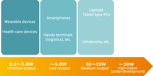
TDK has responded to meet the standards for low-output and medium-output type devices such as smartphones and laptops, in addition to high-output type device over 15W, while developing a diverse range of custom standard-compliant products in an area of small coils for below-2W ultra-low output devices to assist wireless power transfer of ultra-small, thin-profile wearable and/or health-care devices.
TDK's wireless power transfer system products with their output types and main applications are illustrated in Figure 6.
With regard to wireless power transfer of ultra-small, thin-profile wearable and/or health-care devices, electromagnetic induction system with simple principle and structure as described earlier is viewed as the strong candidate. The disadvantage of this conventional electromagnetic induction system is inability to charge more than one device at a time. TDK has overcome this issue, by developing an improved, small, low-output wireless power transfer system based on electromagnetic induction system.
Technologies required for wireless power transfer of wearable devices and hearing aids, etc.
There are a variety of wearable products on the market including wristwatch-type, wristband-type, and jewelry-type. As these small electronic devices can only hold small batteries inside, compared with other portable products, it requires frequent charging. Some of the connector designs for charging including plug-in connector and contact-type, are prone to problems of terminal damage or corrosion that result in charging failure.
Electromagnetic induction-based wireless power transfer system will solve these issues, offering an advantage to accommodate future device size reduction. One challenge that conventional electromagnetic induction system faced was in relation to the highly accurate positioning required of transmission and receiving coils, which made it difficult to charge multiple device simultaneously (Figure 7).
TDK's new, small, low-output wireless power transfer system works as a solution to these issues.
It is a ground-breaking system, based on electromagnetic induction-based wireless power transfer technologies, yet capable of simultaneous, multi-device charging with improved positioning flexibility which had been a restriction imposed in the electromagnetic induction previously.
Figure 8 shows a prototype small, low-output wireless power transfer system presented at MEDTEC 2016 as a sample exhibit. Users simply put a power-receiving unit in the pot-shaped transmission unit, to activate position-free, automatic charging. Its ability to charge multiple devices simultaneously makes itself extremely convenient to use, not only for small wearable products but also for hearing aids with small button batteries as it will eliminate the need for battery replacement. It will also make it easier to produce fully water-proofed devices, offering an easy cleaning and sterilization.
- No troublesome charging process
(start position-free charging by simply placing a device inside) - Simultaneous, multi-device charging capability
- Ultra-small wireless power transfer system not restricted by product size
- No-connector design makes full water-proofing feasible
- Optimum charging environment can be proposed through flexible transmission/receiving system production
Figure 8 TDK's new, small, low-output wireless power transfer system (prototype)
In recent years, we see more high-function IC cards with built-in finger-print authentication and display functions (called smartcard, displaycard, etc.) being in use. These high-function IC cards require frequent charging of their built-in rechargeable batteries due to their large power consumption. Figure 9 illustrates TDK's prototype wireless power transfer system capable of charging up to 10 high-function IC cards simultaneously. This save the time required drastically when compared with using of single-device charging systems.
Charges up to 10 high-function IC cards (smartcard, displaycard, etc.) at the same time.
Figure 9 Multi-device capable, wireless power transfer system (prototype)
Features of TDK's small, low-output wireless power transfer system
Many technologies, such as the fields of magnetic material, magnetic circuit engineering, high-frequency, and simulations, are indispensable components in constructing electromagnetic induction-based wireless power transfer system for small electronics including wearable and/or health-care products, and hearing aids. TDK prides in itself on its ground-up, comprehensive core technology expertise including ferrite-focused material technology, which we have developed and built on over many years. TDK can offer optimum high-efficiency systems tailored to client's needs, as represented in its small coils (transmission and receiving coils) essential for small, low-output wireless power transfer system, and coil modules integrated with control circuits.
«Features of TDK's small, low-output wireless power transfer system»
- Ultra-small coil technology: develops and provides ultra-small transmission/receiving coils customized for product shapes and sizes.
- Custom transmission/receiving system development: proposes system options to achieve maximum efficiency.
- High-performance flexible magnetic sheet: offers a wide selection of TDK's magnetic materials to choose from.
- Custom output engineering available: can accommodate various engineering needs in output designs.


