Solution Guides
Vol.2 Application to EV Wireless Power Transfer Systems Overview
Through advancements in materials technology, multilayer technology, etc., MLCCs (multilayer ceramic chip capacitors) are becoming smaller and achieving higher capacitance. Amidst these circumstances, in recent years, there have also been significant increases in withstand voltage and capacitance of MLCCs used in temperature compensation (class 1).
TDK has developed high voltage MLCCs with C0G characteristics. Through C0G characteristics, these MLCCs achieve a withstand voltage of 1000V at the broadest capacitance range (1nF to 33nF) in the industry. Even in fields where film capacitors have traditionally been used, replacement with MLCCs is now possible for use in resonance circuits, etc.
In addition to explaining the characteristics of C0G MLCCs with high withstand voltage, this section focuses on the advantages of replacing the film capacitors used in EV wireless power transfer systems.
Example of replacing film capacitors with MLCCs: EV wireless power transfer systems
The use of wireless power transfer stated on a large scale with smartphones and is spreading to other devices. The C0G MLCCs produced by TDK feature compact size and superior temperature characteristics. Therefore, they are widely used as resonance capacitors in wireless power transfer for mobile devices. TDK is engaged in technological development for wireless power transfer in EVs (electric vehicles).
From the perspective of environmental issues and fuel economy, major automotive manufacturers throughout the world are focusing on EVs as the most prevalent eco cars, and a variety of EV models are being developed. An essential aspect of popularizing EVs is improving infrastructure, such as charging facilities, and increasing driving distance. In terms of charging infrastructure, an increasing number of charging stands are being installed in parking lots at highway service areas/parking areas, airports, and shopping malls. An especially promising type of charging infrastructure is wireless power transfer systems which enable non-contact charging. Furthermore, wireless power transfer is also an essential technology for practical implementation of autonomous driving.
In addition to electromagnetic induction wireless power transfer for charging built-in batteries in mobile devices, in recent years, TDK has been one of the first companies to start developing magnetic resonance wireless power transfer technology. Until now, we have supported needs in industrial equipment such as automated guided vehicles (AGV), elevators, etc. The EV wireless power transfer introduced in this section is an advanced magnetic resonance system that utilizes TDK's magnetic material technology and dielectric technology.
Principles and features of magnetic resonance wireless power transfer
The system of the widely used electromagnetic induction wireless power transfer is equivalent to structures in which transformer cores are divided and gaps are opened. The advantage of this method is that it can be achieved at a low cost. However, the transmitting efficiency decreases drastically when the gap between the transmission coil and receiving coil becomes large. As the distance between the coils increases, a portion of the magnetic flux becomes leakage flux, which weakens magnetic coupling between coils. Magnetic coupling is expressed as the coupling coefficient (k). The coupling coefficient is in the range of 0≦k≦1. The ideal value, without leakage flux, is 1. It decreases as leakage flux increases from an increase in the gap between coils or a shift of the coil center, and it ultimately declines to 0. Magnetic resonance wireless power transfer was developed as a method for overcoming these disadvantages.
In the magnetic resonance method, an LC resonance circuit is formed by inserting capacitors in both the transmission side and receiving side, thus achieving power transmission which matches the resonance frequency of the transmission side and receiving side. This method maintains a high transmitting efficiency even in conditions with a low coupling coefficient due to slight widening of the distance between coils or a shift of center position, etc. The basic principles of this method are shown in Figure 1.
Figure 1: Basic principles of magnetic resonance wireless power transfer
High-power resonance capacitors are an important component in magnetic resonance using wireless power transfer EV charging systems. This is because a high-accuracy resonance circuit with high withstand voltage is required for efficient wireless transfer of a large amount of power in a short time.
Film capacitors are one valid option as capacitors that satisfy these requirements. However, for EVs that require further downsizing and weight reduction in order to increase cruising distance and achieve a more spacious vehicle cabin, a significant advantage is achieved through replacement with C0G MLCCs that save space. Previously, there were no products which achieved withstand voltage of 1000V with C0G characteristics. However, the high voltage MLCCs with C0G characteristics developed by TDK can now be used as effective replacements.
Achieved even greater reductions in size and weight by replacing with 1000V C0G MLCC
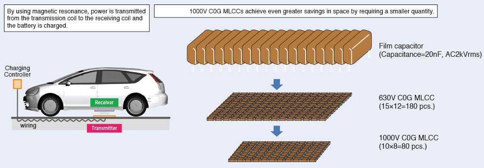
Figure 2 shows an image of EV battery charging using magnetic resonance wireless power transfer, and a size comparison of resonance capacitors on the receiving side.
Figure 2: EV battery charging using magnetic resonance wireless power transfer & size comparison of resonance capacitors for the receiving side (image)
If using multiple TDK C0G MLCCs connected in serial and parallel arrays to replace film capacitors which satisfy the specifications of capacitance 20nF and AC 2kVrms, you would need 180 of the conventional 630V C0G MLCCs. This equates to a significant savings in space. However, when replacing with the newly-developed 1000V C0G MLCCs, simple calculations indicate that only 80 MLCCs would be required, saving even more space.
Enables significant reduction in the number of MLCCs used through extremely low ESR
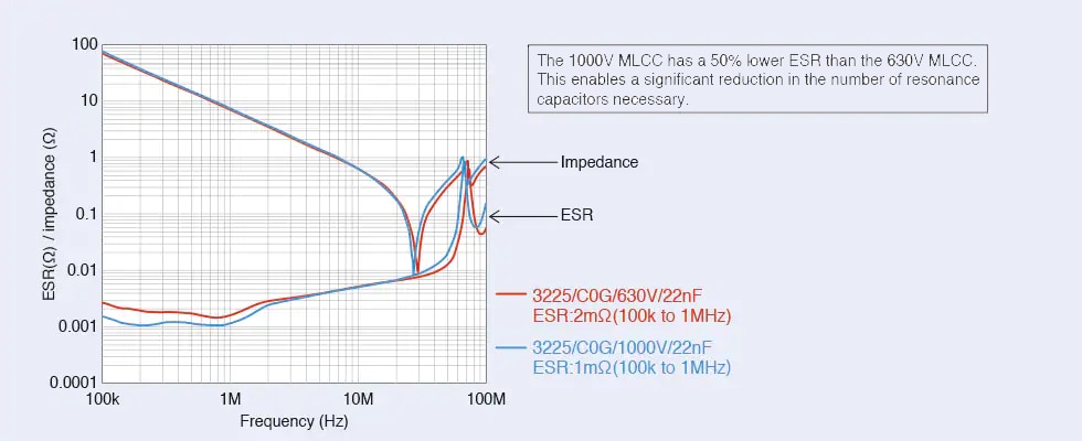
Figure 3 shows a comparison of impedance-frequency characteristics and ESR-frequency characteristics for the conventional 630V C0G MLCC and the newly-developed 1000V C0G MLCC.
Figure 3: Comparison of impedance-frequency characteristics and ESR-frequency characteristics for 630V MLCC and 1000V MLCC
Compared to the 630V MLCC, the ESR for the 1000V MLCC is 50% less. When the rated voltage is increased from 630V to 1000V, the current flowing through a single MLCC increases by approximately 1.5 times. If the ESR value is equivalent to conventional MLCCs, there is an increased risk of lifespan degradation from heat generation.
Since the newly-developed 1000V C0G MLCC has a 50% lower ESR, as shown by the replacement example in Figure 2, it is possible to achieve the significant reduction of 180 MLCCs to 80. This clearly shows the importance of the ESR value when using MLCCs to replace other capacitors.
Automotive Grade MLCC (multilayer ceramic chip capacitor) CGA series C0G characteristics
TDK has mid voltage MLCCs (rated voltage 100 to 630V), high voltage MLCCs (rated voltage of 1000V and higher), and other MLCCs in our automotive grade CGA series. In this series, we offer the following as products with a rated voltage of 1000V, C0G temperature characteristics, and capacitances of 1nF to 33nF. In addition to resonance capacitors for magnetic resonance wireless power transfer, these MLCCs can also be used to replace film capacitors in applications which require high accuracy, such as time constraint circuits, filter circuits, oscillation circuits, etc. for downsizing and surface mount technology (SMT). Furthermore, for even greater reliability, TDK offers a MEGACAP type and a soft termination series which are highly resistant to external environmental stresses such as board bending that causes body cracks, heat shock which causes solder cracks, and vibration.
Wireless power transfer technology for efficient charging of batteries is the key to automotive evolution such as EVs and autonomous driving. In magnetic resonance wireless power transfer, resonance capacitor characteristics are closely related to power transmission efficiency. TDK's high voltage MLCCs with C0G characteristics that achieve withstand voltage of 1000V are temperature compensation (class 1) MLCCs. They possess optimal characteristics as resonance capacitors in EV wireless power transfer.
Another important element of high voltage MLCCs with C0G characteristics is extremely low ESR. TDK will continue to work at further enhancing our product lineup by improving withstand voltage, capacitance range, and other characteristics.
| Series | External dimensions (L x W) | Temperature characteristics |
Rated voltage | Capacitance |
|---|---|---|---|---|
| CGA6 | 3.2x2.5mm (EIA 1210) |
C0G* | 1000V | 1nF to 22nF |
| CGA9 | 5.7x5.0mm (EIA 2220) |
C0G | 1000V | 10nF to 33nF |
* C0G: From -55 to +125°C, the temperature coefficient is within 0±30ppm/°C


