Ferrite coils support NFC circuits ideally

Rapid worldwide adoption of NFC-equipped devices is forecast
NFC, a technology invented more than 10 years ago, has been spreading rapidly throughout the world in recent years. In Japan, systems adopting non-contact type IC cards such as mobile payment systems, e-money, and payments at the ticket barriers of stations are already common, and they are also helping to expand the use of NFC functionality. It is expected that applications of NFC functionality will become more numerous throughout the world in the future, at the same time as the number of NFC-equipped devices in use grows.
Figure 1 is a schematic diagram of a typical NFC circuit. An LC filter circuit made up of a coil and capacitor is inserted between the antenna and control IC.
It is necessary to minimize variations between the inductance of the coil and the capacitance of the capacitor since they affect impedance matching. Also, a narrow tolerance (inductance value of ±5% or smaller) and properties that are stable even after going through a reflow furnace or current energization are required of the coil. Moreover, a high Q value is required since low loss is required at a communication frequency of 13.56MHz. TDK’s new multilayer ferrite coil, the MLJ1608 series, satisfies such requirements.
The MLJ1608 series consists of coils that are optimally designed to offer the characteristics required by NFC circuits. In addition, since the coils maintain a high Q value at frequencies up to approximately 70MHz, they produce low loss in signal lines, as well as providing a much improved DC bias characteristic, making them suitable for use in power lines. The following introduces the excellent characteristics of the MLJ1608 series, which are greatly superior to the characteristics of existing products.
Figure 1 Schematic diagram of NFC circuit
New ferrite material produces low-loss characteristic
When an NFC circuit is communicating, an AC signal flows through it. When an AC signal flows through the ferrite coil, core losses, including eddy-current loss, hysteresis loss, and residual loss, occur. Normally, the characteristics of a ferrite material are expressed by a B-H curve, and a small B-H curve called a minor loop appears within the range of the AC current’s amplitude. The size of this minor loop determines the magnitude of the core losses.
As shown in Figure 2, the ferrite material used today has a high residual magnetic flux density, which makes for a large minor loop. In contrast, the new ferrite material features a low residual magnetic flux density, which makes for a small minor loop. In the MLJ series, core losses have been considerably reduced because of the use of this low-loss ferrite material, resulting in a low-loss characteristic which supersedes that of the existing MLF series products, as well as that wound coil products (Figure 3). Low-loss characteristics contribute to the improvement of communication characteristics in general, as well as helping to reduce power consumption.
Figure 2 Comparison of the B-H curves of the existing ferrite material, and the new low-loss ferrite material (model)
Figure 3 Comparison of power loss between the existing product and the MLJ1608 series
Considerable improvement in DC-bias characteristic
In conventional control ICs for NFC systems, the existing MLF1608 devices have been used as reference coils, because the majority of these ICs only drew a small amount of current during communication. However, in recent years, ICs requiring a high current during communication have become more common, and the rated current of the MLF1608 series is no longer high enough.
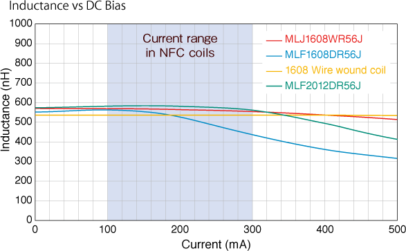
The MLJ series uses a newly developed low-loss high-current ferrite material. This new ferrite material has DC-bias characteristics more than twice as good as those of the existing MLF series, while maintaining an equivalent performance level. Because of these improved DC-bias characteristics, the MLJ1608 series has been able to achieve a rated current greater than that of MLF2012 type, a device which is one size larger.
NFC circuits draw an AC current ranging from approximately 100mA to 300mA during communication. Over this range, the MLJ1608 series products exhibit characteristics equivalent to those of a wire-wound coil thanks to the improvement in DC-bias characteristics (Figure 4).
Figure 4 Comparison of DC-bias characteristics between existing products and the new MLJ1608 series
Q characteristic: values in the conducting state are important
Since NFC operates at a frequency of 13.56MHz, system designers require coils that exhibit high Q values at this frequency. Generally, the Q characteristic is described in catalogues, and there is no problem as long as the product is used at currents lower than the rated maximum. However, since a large current of up to 300mA flows in an NFC circuit, the Q characteristic deteriorates if a general multilayer ferrite coil for signal lines is used. Therefore, the Q characteristic in a conducting state is important in an NFC circuit. As is shown in Figure 5, the Q characteristic of the MLJ series yields an extremely mild degradation curve and ensures a characteristic equivalent or superior to that of the wire-wound coil products in the range of the current that flows in NFC circuits.
Figure 5 Comparison of Q characteristics between the existing products and MLJ series in a conducting state
Responding to Smaller Footprints and Higher Current with an Expanded Lineup
To respond to diverse impedance matching needs, the inductance lineup of the MLJ series is being expanded and 1005-type products were added to support high-density mounting.
Also, the MLJ1005H series, which uses ultra-low loss ferrite materials that reduce core losses to extremely low levels, has been added to support the increased functionality of NFC control ICs. In the current range greater than 300 mA, Q characteristics better than the conventional MLJ1005 series are achieved, surpassing wound coil products.
Figure 6. Comparison of Q Characteristics of Earlier Products and the MLJ1005 Series When Energized by Current
AC Resistance Improved to Increase Reception Sensitivity
It is important to curtail inductor losses at 13.56 MHz, the frequency used for communication, in order to prevent a decrease in antenna output.
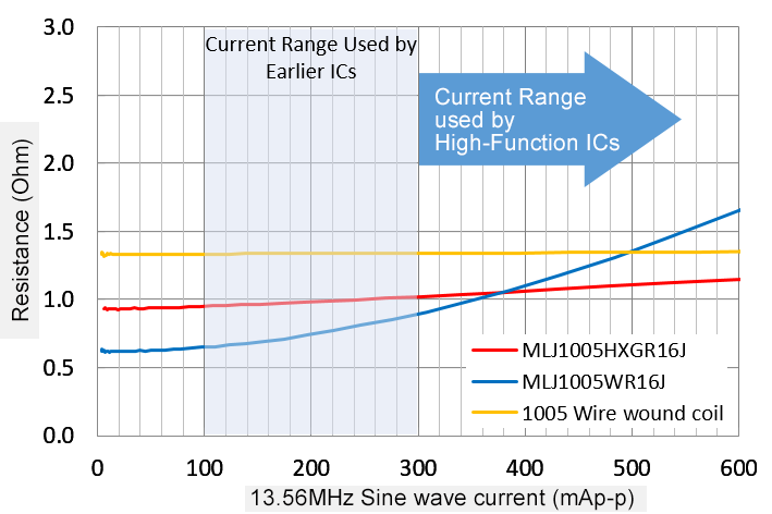
To do this, it is necessary to keep AC resistance (Rac) low and to maintain the low Rac when current flows.
With the MLJ-W series, TDK has achieved low Rac, and the new MLJ-H series achieves low Rac even when under high current.
As you can see in Figure 8, the Rac of the MLJ1005H remains low even when under high current.
Figure 7. Comparison of Rac Characteristics of Earlier Products and the MLJ1005 Series When Energized by Current
Magnetic shield structure allows for flexible design of the mounting position
In recent years, the packaging density of the electronic components in smartphones and other electronic devices has increased, at the same time as the number and quality of their functions has grown. This gives the designer less flexibility to choose where to mount components on the board. In addition, coils which are prone to magnetic flux leakage might cause magnetic coupling if mounted too close to certain other components, resulting in undesirable variations in operating characteristics.
The MLJ series eliminates this problem, since it adopts the same magnetic shield structure as the existing MLF series. This enables high-density packaging and a flexible choice of component mounting positions.
Figure 8 Comparison of magnetic flux leakage between a multilayer coil and a wire-wound coil
Comparison of coils' communication characteristics
The MLJ series not only features superior characteristics as a coil, but exhibits excellent communication characteristics when used as a coil in NFC circuits as well. Tests conducted by the NFC Forum (an industry association that establishes technical or test specifications for NFC) have measurement points at 5mm intervals on three axes (green dots in Figure 9). Figure 8 shows the result of the comparison of the voltages at Z = 5mm in the horizontal and vertical directions, as well as a comparison of the voltages at reference points up to 10mm (reference values), although the latter ones are out of the measurement range of the NFC Forum. The line at 3.14V is the required voltage in this test. The higher the voltage, the better the NFC communication characteristics. The MLJ series ensures voltages exceeding those of the wire-wound coil in this test.
As has been described, the MLJ series products are optimally designed for NFC circuits, offering properties better than those of wire-wound coils.
Figure 9 Outline of the NFC Forum’s method for evaluating communication characteristics
Figure 10 Comparison of the communication characteristics of the MLJ1608 and of a wire-wound coil
Conclusion
The advantages of the MLJ series are derived from its use of the new low-loss ferrite material that TDK has developed. TDK's world-class material development technologies enable it to create products with properties that are equivalent or superior to those of wire-wound coils. The ferrite material developed for the MLJ series is a revolutionary material. TDK intends to develop more new products benefiting from the superior performance achievable with this outstanding new ferrite material.
FEATURES, APPLICATIONS AND ELECTRICAL CHARACTERISTICS
Main features
- Newly developed ferrite material enables high current rating.
- Precise lamination provides for tight tolerances.
- Ferrite material significantly reduces high-frequency losses.
Main applications
- NFC circuits in smart phones and PCs, power supply lines in various electronic devices
Main Specifications
| Serie | MLF1608D MLF1005V |
MLJ1608W MLJ1005W |
MLJ1005HIn Entwicklung |
|---|---|---|---|
| Art | STD | Hochstrom Low Loss (Geringer Verlust) |
erhöhte Spannung (Hochstrom) Super Low Loss (Supergeringer Verlust) |
| Größe [mm] | 1608 / 1005 | 1608 / 1005 | 1005 |
| L Toleranz [%] | +/- 5 | +/- 5 | +/- 5 |
| L-Wert [uH] | 0.10 – 0.82 (1608 size) 0.10 – 0.56 (1005 size) |
0.10 – 0.56 (1608 size) 0.075 – 0.56 (1005 size) |
0.056 - 0.20 |
| Aktuell [mA] | 70 – 200 (1608 size) 120 – 180 (1005 size) |
400 – 800 (1608 size) 250 – 550 (1005 size) |
480 - 950 |


