High Voltage Compatible! C0G Characteristic Capacitor for Resonant Circuits that Supports Higher Output and Miniaturization of Automotive OBCs

In order to meet this demand, TDK has released a new autograde C0G MLCC series with a rated voltage of 1250 V.
Through an example of the operation of a resonant capacitor in an LLC resonant converter, we will introduce why we recommend a 1250V rated C0G MLCC.
Why are MLCCs the best choice for capacitors for resonant circuits?
It has the following features and is suitable as a capacitor for resonant circuits in automotive OBCs and wireless power transfer.
- High allowable voltage and current
- It is possible to construct a resonant capacitor bank with fewer capacitors, contributing to miniaturization.
- C0G characteristics: Even with temperature and/or DC/AC voltage variations, the change in capacitance is small.
- Excellent capacitance and impedance stability over temperature and voltage ensure that the resonant frequency remains constant, and energy transmission characteristics are stable. In addition, since the loss is small, self-heating is minimized and transmission efficiency is improved.
- Automotive grade with AEC-Q200
- This product complies with AEC–Q200, the global standard for reliability testing and qualification standards for automotive electronic components.
- There are two types of tolerances: J tolerance (±5%) and G tolerance (±2%).
- High-precision resonance contributes to the improvement of transmission efficiency.
Purpose of the evaluation
LLC resonant converters are widely used in automotive OBCs as high-efficiency DC/DC converters. The resonant capacitors used in LLC resonant converters are subjected to high voltages and currents that typically exceed the withstand capabilities of a single capacitor. Therefore, capacitors are used in series and parallel configurations to meet the acceptable voltages and currents. The use of capacitors with higher voltage tolerances not only reduces the number of series, but also allows the required capacitance to be achieved with a smaller number of parallels.
In this solution guide, we will introduce examples of heat generation suppression and miniaturization of capacitor banks that can be achieved by using MLCCs with a rated voltage of 1250V.
Evaluation circuit configuration (LLC resonant converter)
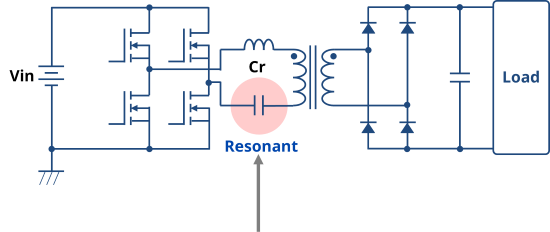
Figure 1 shows the schematic of the full-bridge LLC resonant converter used for evaluation.
The capacitance of the resonant capacitor Cr is 50 nF, and the capacitor bank is configured to satisfy the allowable voltage and current of the capacitor. The configuration of this resonant capacitor was replaced and the following items were evaluated.
LLC Converter Operating Conditions
Input voltage Vin
Output voltage Vo
Output power Po
Operating Frequency Fsw
Resonant capacitor Cr
:400V
:475V
:4.3kW
:133kHz
:50nF
Capacitors to evaluate
・Film capacitors
・MLCC (C0G characteristics, rated voltage: 630V)
・MLCC (C0G characteristics, rated voltage: 1250V)
Evaluation items
・Operating waveform
・Surface temperature of the resonant capacitor
・Mounting area, product height
■Evaluation circuit
Full-Bridge LLC Resonant Converters
■Operating conditions
Vin = 400V
Vo = 475V
Po = 4.3kW
Fsw = 133kHz
Cr = 50nF
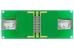
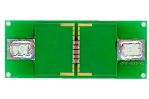
| Company A Film Capacitors | TDK ・ MLCC(C0G/630V) | TDK ・ MLCC(C0G/1250V) | ||
|---|---|---|---|---|
| appearance | ||||
| Specifications of a single item | Name | - | CGA5L4C0G2J103J160AA | CGA6P1C0G3B103J250AC |
| Chip Size (mm) |
13.0×5.0 | 3.2×1.6 | 3.2×2.5 | |
| Height (mm) |
11.0 | 1.6 | 2.5 | |
| Rated voltage | 600V(AC) | 630V | 1250V | |
| Capacitance | 10nF | 10nF | 10nF | |
| Type | polypropylene | C0G (Class 1) | C0G (Class 1) | |
| Capacitor bank specification | Total Capacity | 50nF | 50nF | 50nF |
| Number of series | 2pcs | 2pcs | 1pc | |
| Number of parallels | 10pcs | 10pcs | 5pcs | |
| Number of MLCCs | 20pcs | 20pcs | 5pcs | |
Comparison of Operating Waveforms - Equivalent to Film Capacitors
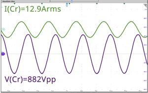
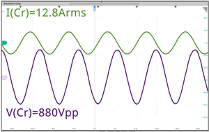
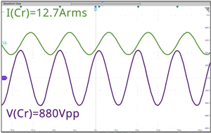
Figure 2 shows the voltage and current applied to the capacitor bank when the LLC resonant converter is operated.
Even if you change the configuration of the capacitor bank, you can see that the same load is applied.
| Film Capacitor(10nF) | MLCC(C0G/630V/10nF) | MLCC(C0G/1250V/10nF) | |
|---|---|---|---|
| configuration | 2 series, 10 parallel, 50nF | 2 series, 10 parallel, 50nF | 1 series, 5 parallel, 50nF |
| Operating waveform |
|||
| voltage | 882Vpp | 880Vpp | 880Vpp |
| current | 12.9Arms | 12.8Arms | 12.7Arms |
Comparison of surface temperatures of resonant capacitors - Heat generation suppression is possible
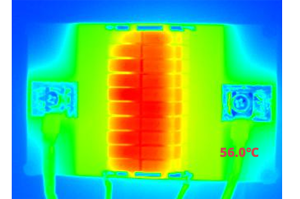
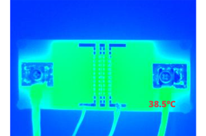
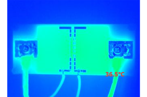
Figure 3 shows the surface temperature of the capacitor bank during LLC resonant converter operation.
It can be seen that the heat generation of MLCCs is almost the same, but the film capacitor has more self-heating than MLCCs.
This is thought to be due to the fact that the ESR of the C0G characteristic MLCC is smaller than that of the film capacitor, and the self-heating is suppressed. By using MLCCs, it is possible to handle high power in a smaller mounting area.
| Film Capacitor (10nF) | MLCC (C0G/630V/10nF) | MLCC (C0G/1250V/10nF) | ||
|---|---|---|---|---|
| appearance | ||||
| Thermal Imaging | ||||
| Capacitor Bank Maximum temperature | 56.0℃ | 38.5℃ | 36.5℃ |
Comparison of mounting size and product height - 97% reduction in mounting area!
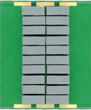
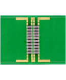
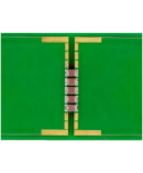
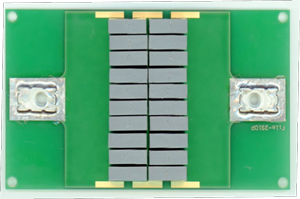
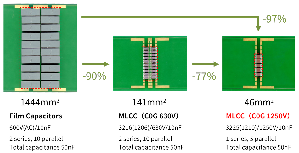
Figure 4 shows a comparison of the mounting area when a capacitor bank is configured.
- When comparing film capacitors and MLCCs (C0G/630V), even if the number of units is the same, the mounting area of MLCCs is reduced by 90% due to their small size.
- MLCCs (C0G/1250V) have a high rated voltage, so it is possible to reduce the number of series units. Therefore, it is possible to achieve a target capacitance of 50 nF for a resonant capacitor with a smaller number of components for a product with the same capacitance.
As a result, the footprint is reduced by 77% when comparing MLCCs (C0G/630V) and MLCCs (C0G/1250V).
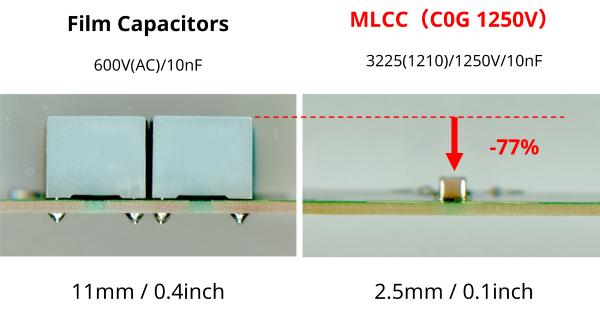
Figure 5 shows a comparison of product heights. By replacing film capacitors with MLCCs, it is possible to reduce the profile and mount the surface.
Summary
Using resonant capacitors in LLC resonant converters as an example in this solution guide, we have introduced examples of heat generation suppression and miniaturization that can be achieved by using C0G characteristic MLCCs with a rated voltage of 1250 V,
- Even with a change in the type of capacitors in the resonantant bank, the operating waveforms are almost the same.
- By replacing film capacitors with MLCCs, it is possible to reduce the mounting area, reduce the profile, make it surface-mounted, and reduce self-heating (extending the OBC service life).
- In addition, by using a C0G characteristic MLCC with a rated voltage of 1250V, it is possible to reduce the number of MLCCs and reduce the mounting area while meeting the allowable voltage and current. Reduction in component count extends the MTTF for the OBC application.
Based on the above results, the use of high-voltage MLCCs makes it possible to handle high power in a small area, contributing to the miniaturization of high-output OBCs.
Product Lineup
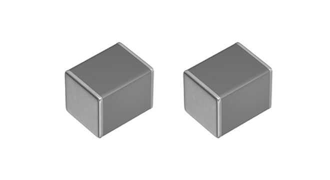
TDK has released a new C0G characteristic MLCC with a rated voltage of 1250 V for automotive grade.
The allowable voltage and current are higher than those of conventional products, and the capacitance changes little with respect to temperature and DC/AC voltage, making them suitable as capacitors for resonant circuits.
Two tolerances are available: ±5% and ±2%.
| Chip Size |
CGA5 3216(1206) |
CGA6 3225(1210) |
CGA9 5750(2220) |
|||||
|---|---|---|---|---|---|---|---|---|
| R.V. | 2J 630V |
3B 1250V |
3A 1000V |
2J 630V |
3A 1000V |
2J 630V |
||
| Cap. | 102 | 1nF | NEW | |||||
| 122 | 1.2nF | NEW | ||||||
| 152 | 1.5nF | NEW | ||||||
| 182 | 1.8nF | NEW | ||||||
| 222 | 2.2nF | NEW | ||||||
| 272 | 2.7nF | NEW | ||||||
| 332 | 3.3nF | NEW | ||||||
| 392 | 3.9nF | NEW | ||||||
| 472 | 4.7nF | NEW | ||||||
| 562 | 5.6nF | NEW | ||||||
| 682 | 6.8nF | NEW | ||||||
| 822 | 8.2nF | NEW | ||||||
| 103 | 10nF | NEW | ||||||
| 123 | 12nF | |||||||
| 153 | 15nF | |||||||
| 183 | 18nF | |||||||
| 223 | 22nF | |||||||
| 333 | 33nF | |||||||
| 683 | 68nF | |||||||
| 104 | 100nF | |||||||
What are the precautions for selecting a resonant capacitor?
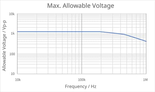
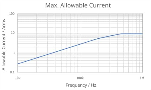
MLCCs have a allowable voltage and current that can be applied depending on the frequency used (Fig. 7). When selecting a resonant capacitor, refer to the allowable voltage graph and allowable current graph on each product page in the Product Center, and consider the configuration of the capacitor bank so that both the voltage and current applied to the capacitor do not exceed the allowable voltage and current.
The allowable voltage graph and allowable current graph are created based on the following conditions:
- The voltage and current waveforms applied to the MLCC are assumed to be sine waves of a single frequency.
- The evaluation environment for self-heating temperature is room temperature and natural convection.
- The substrate on which the MLCC is mounted is a substrate with sufficient heat dissipation capacity for the applied current, and is evaluated in a state of thermal equilibrium under natural convection.
- The allowable voltage and allowable current are determined so that the self-heating temperature rise of the MLCC is 20°C or less under the above conditions.
- This data is for reference only and does not guarantee reliability.
The allowable voltage and current data can be downloaded from the following as a ZIP file.
CGA6P1C0G3B103J250AC
Detailed materials of medium-to-high-voltage MLCCs for resonant circuits and allowable voltage/allowable current data
TDK_MLCC1250V_DL_en
dm_t129_1250v

