MLCC Solutions for Power Supply Circuits (Verification of Optimal Structures for Output Capacitors)

Contents
- Capacitor requirements within electrical characteristics
- Verification of optimal structures for output capacitors
- Effects of low-ESR and stability as a result of increased use of MLCC
- Example of countermeasures in cases where margins are insufficient: Adjustment of phase compensation units
- Verification of optimal structures for output capacitors: Summary
- Contact
Capacitor requirements within electrical characteristics
The equation and an image of voltage fluctuation at fixed loads and variable loads are indicated below.
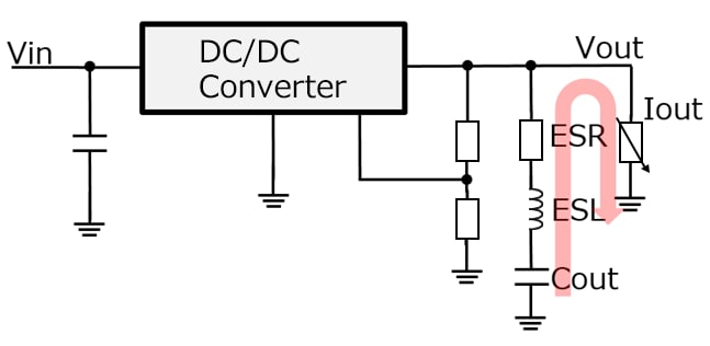
In conjunction with shift to higher current (higher Δiout) and faster operation (higher dΔiout/dt), the range of voltage fluctuation when the load varies has increased in comparison with voltage fluctuation when under fixed load, and in order to control the fluctuation within the desired voltage range, a capacitor structure with high capacitance, low ESR, and low ESL is necessary.
| Voltage fluctuation when under fixed load (ripple voltage) | Voltage fluctuation when under variable load | |||||||||
|---|---|---|---|---|---|---|---|---|---|---|
| ΔV out = ΔIL × ESR + ESL × | Vin | + | ΔIL | ΔV out = Δiout × ESR + ESL × | dΔiout | + | 1 | ∫ Δioutdt | ||
| L | 8 × c × Fsw | dt | c | |||||||
In cases where the current supplied by a DC-DC converter cannot follow the load fluctuation, the capacitor act as a backup, supplying the load with the current it needs until the power supply can catch up.
Many large capacitors, such as conductive polymer capacitors, have long been used in high-speed and high-current lines to stabilize the power supply and provide instantaneous power.
This document verifies the effectiveness of replacing conventional conductive polymer capacitors with MLCCs, which are characterized by low ESR and low ESL, to suppress voltage fluctuation including maintaining the stability (frequency characteristics) of the power supply.
Verification of optimal structures for output capacitors
Optimal output capacitor structures are verified for the two structures indicated in (1) and (2) below under the evaluation conditions specified below.
The following evaluation conditions and items are verified.
| Output capacitor structure | ① | ② |
|---|---|---|
| Total capacitance [μF] | 990 | 1000 |
| Conductive polymer capacitor (2.5V 7343 330μF) |
3pcs | |
| MLCC CGA6P1X7T0G107M250AC (4.0V 3225 100μF) Automotive products—Currently in mass production |
10pcs |
Evaluation conditions
- ◆ Input voltage: 12V
- ◆ Output voltage: 1.5V
- ◆ Switching frequency: 400kHz
- ◆ Load current (Δiout): 30A
- ◆ Slew rate (Δiout/dt): 100A/μsec
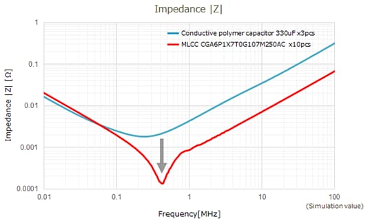
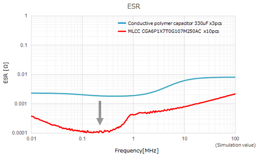
MLCCs have excellent ESR and ESL characteristics compared to conductive polymer capacitors.
ESR and ESL can be reduced by replacing conductive polymer capacitors with MLCCs.
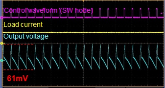
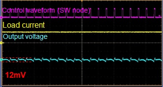
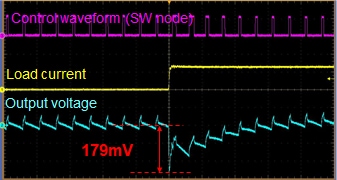
Voltage fluctuation when under fixed load and variable load can be controlled using the MLCCs in structure (2).
As indicated in the impedance/ESR characteristics, the MLCCs indicated in structure (2) make possible low ESR and low ESL and control voltage fluctuations.
| Structure | Conductive polymer capacitor | MLCC(After adjustment) |
|---|---|---|
| Product / Specifications | 2.5V 7343 330μF x3pcs | CGA6P1X7T0G107M250AC
x10pcs 4.0V 3225 100μF |
| Total capacitance [μF] | 990 | 1000 |
| Voltage fluctuation [mV] When under fixed load Δiout:30A |
||
| Voltage fluctuation when under load fluctuation (rising) [mV] Δiout:0A→30A Δiout/dt:100A/μs |
Verification of optimal structures for output capacitors
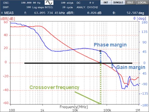
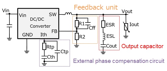
It is shown that increasing the number of MLCCs is effective for suppressing voltage fluctuation, but in general, stability tends to decrease depending on the specifications of the power supply IC due to the effect of low ESR caused by the increase in the number of MLCCs. Because of this, it is important to confirm the relationship between responsiveness and stability of the power supply by acquiring and confirming a board diagram indicating the frequency characteristics of the power supply IC using a frequency response analyzer (FRA) or other such equipment. Also, stability can generally be adjusted by adjusting the constants of the capacitors and resistors in the external phase compensation circuit and feedback section of the power supply circuit block diagram as shown below.
The specific adjustment methods and so on will vary depending on the power supply IC used. Please contact the IC manufacturer directly regarding adjustment methods.
| Item | Key Points | Effect on voltage fluctuation |
|---|---|---|
| Crossover frequency | Higher means faster operation ⇒ Effect on responsiveness |
Reduction in voltage fluctuation |
| Phase margin/gain margin | Higher means stable operation ⇒ Effect on stability |
Prevents ringing and abnormal operation |
Example of countermeasures in cases where margins are insufficient: Adjustment of phase compensation units
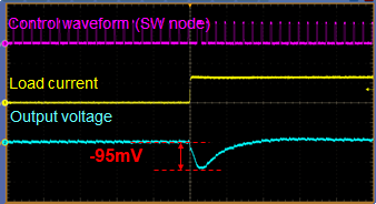
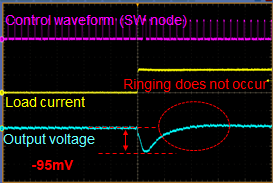
The waveform during variable voltage due to adjustment of the phase compensation unit is indicated below.
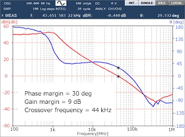
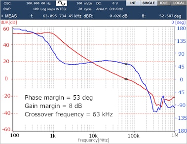
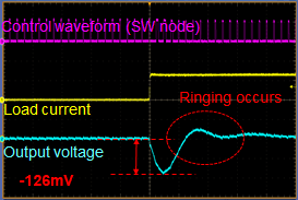
Compared to before adjustment, after adjustment, the voltage fluctuation is reduced by 31 mV by speeding up the crossover frequency from 43 kHz to 63 kHz.
Also, it can be seen that after adjustment, the phase margin increases from 30 deg to 53 deg and stability is improved due to the absence of the ringing wave form observed before adjustment. If a frequency response analyzer (FRA) is not available, stability can be determined by whether ringing or oscillation occurs during waveform observation, so check the stability during measurement.
| MLCC phase compensation units | Before adjustment | After adjustment |
|---|---|---|
| Voltage fluctuation [mV] When under fixed load Δiout:30A |
||
| Voltage fluctuation when under load fluctuation (rising) [mV] Δiout:0A→30A Δiout/dt:100A/us |
||
| Whether ringing occurs is an indicator of stability | ||
Verification of optimal structures for output capacitors: Summary
A summary of the evaluation results is set forth below.
- Under a high-current, high-slew rate environment, voltage fluctuations during sudden load changes are greatly affected by the ESR and ESL components of the output capacitors.
MLCCs make possible low ESR and low ESL and can control voltage fluctuations. - Generally, stability (the degree of phase margin) tends to decrease as a result of the low ESR of MLCCs, and in such cases, consider adjusting the constants of the phase compensation circuit.
- When designing the structures of output capacitors, it is necessary to optimize the structure taking into consideration not just voltage fluctuation, but also the power supply stability.
- TDK's high-capacity automotive MLCCs can be used in sets that require high reliability, ensuring better electrical characteristics and reliability.
- TDK has an extensive lineup of components that can be selected to best meet the electrical performance requirements of the circuit used, mounting area restrictions, restrictions on the number of components, and other constraints. The TDK product lineup, data sheets, technical support tools, and more are available on TDK's websites.
| Output capacitor structure | Conductive polymer capacitor | MLCC |
|---|---|---|
| Product / Specifications | 2.5V 7343 330μF x3pcs | CGA6P1X7T0G107M250AC x10pcs 4.0V 3225 100μF |
| Total capacitance [μF] | 990 | 1000 |
| Voltage fluctuation when under fixed load [mV] Δiout:30A |
61 | 12 (-80%) |
| Voltage fluctuation when under rising load [mV] Δiout:30A Δiout/dt:100A/μs |
179 | 95 (-46%) |

