Noise Countermeasures for DC-DC Converter Input Lines using 3-terminal Filters (Feed-through Filters for Power Lines)

Table of Contents
Basic Configuration of an Input Filter
The input line of a DC-DC converter generates significant noise due to input voltage fluctuations caused by switching noise and nth harmonics based on the fundamental frequency during switching. This noise has two modes: common mode and normal (differential) mode, and appropriate components must be selected depending on the noise mode.
As shown in Figure 1, during the initial design stage, a π-type filter consisting of capacitors and inductors (C+L+C) is a desirable pattern configuration for normal mode noise countermeasures. For common mode noise countermeasures, a common mode filter (CMF) is effective.

Normal (differential) Mode Noise and Common Mode Noise
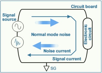
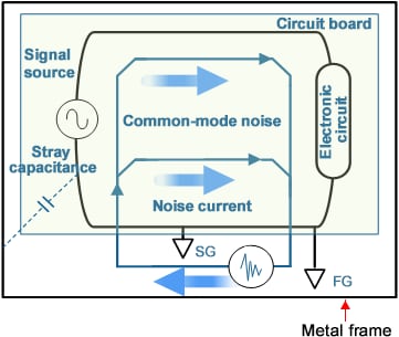
There are two types of conducted noise: normal (differential) mode noise and common mode noise. Normal mode noise is generated between circuit lines and flows in reverse phase, while common mode noise is generated between circuit lines and GND and flows in the same phase. When implementing noise countermeasures, it is important to identify which mode the noise is occurring in and select the appropriate components for mitigation.
For normal mode noise, inductors and capacitors are typically used, while for common mode noise, a common mode filter is effective.
Noise flowing through the circuit line
(flowing in reverse phase of the line)
Noise flowing through the frame ground
(flowing in phase with the line)
Evaluation Conditions for Checking the Effect of Noise Suppression for Each Filter Configuration
As the switching frequency of DC-DC converters increases, the noise level in the FM band also increases. Typically, a π-type filter with a two-terminal capacitor is used, but further noise reduction can be achieved by using a three-terminal feedthrough filter with low ESL characteristics. In this evaluation, we will compare and verify all three configurations of the π-type filter for the following evaluation details.
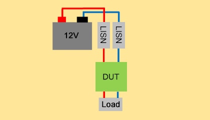
For the conducted noise voltage method, we separate normal mode noise and common mode noise and compare the filter effects.
Conducted noise voltage method is measured with our common mode filter installed as a common mode countermeasure for all three configurations.
Evaluation Contents
- ■DC-DC converter conditions
Input voltage: 12V
Output voltage: 5V
Switching frequency: 2MHz
Output current: 2A - ■Evaluation Items
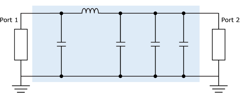
1) Transfer characteristics of π-type filter (S21)
2) Conducted noise voltage method
Evaluation Circuit
*Transfer characteristic (S21) analysis by simulator
■ Measurement place:3m Anechoic chamber
■ Frequency:150kHz-108MHz
Evaluation Configuration
| π-type filter configuration | Configuration 1: No filter | Configuration 2: Capacitor (2 terminals) | Configuration 3: 3-terminal filter (feed-through filter) |
| Wiring image |  |
 |
 |
| C1 | - | 3.2mm×1.6mm, 4.7μF,35V | YFF serie 3.2mm x 1.6mm,1μF,100V,6A Feed-Thru connection* |
| L1 | - | 2.0mm×1.2mm,220Ω at 100MHz,3A | 2.0mm×1.2mm,220Ω at 100MHz,3A |
| C2 | - | 3.2mm×1.6mm,4.7μF,35V | YFF serie 3.2mm x 1.6mm,1μF,100V,6A Feed-Thru connection* |
*For more information on feedthrough connection,
please refer to the following link.
Result After Checking the Effect of Noise Suppression for Each Filter Configuration
Based on the results of checking the effect of noise suppression for each filter configuration, it is found that the 3-terminal filter (feedthrough filter) is highly effective in attenuating noise in the high-frequency range.
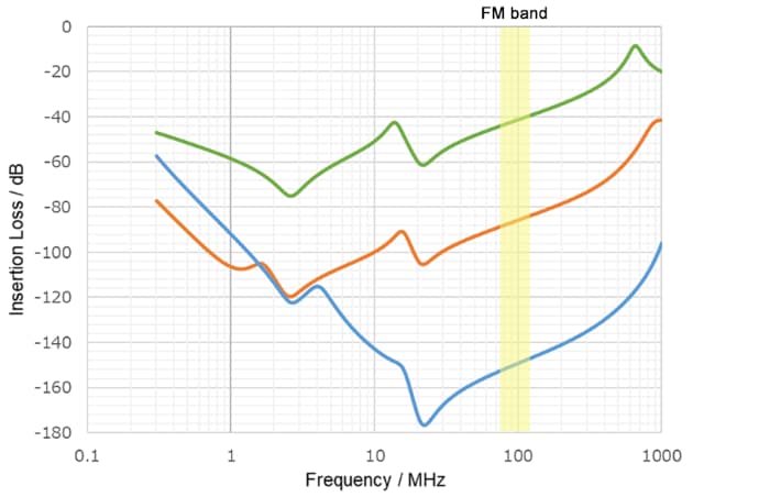
- Configuration 1: No filter
- Configuration 2: Capacitor (two-terminal)

- Configuration 3: Three-terminal filter (feedthrough filter)

The noise level is usually higher in normal mode than in common mode.
To address this issue in normal mode, a π-type filter equipped with a three-terminal feedthrough filter is very effective in suppressing noise in a wide frequency band including the FM band.
Normal mode
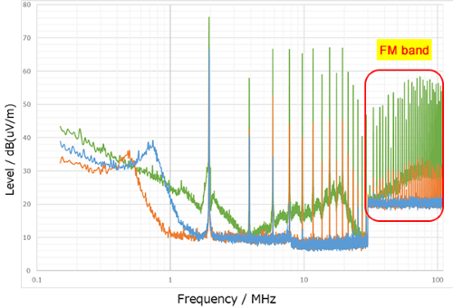
- Configuration 1: No filter
- Configuration 2: Capacitor (two-terminal)

- Configuration 3: Three-terminal filter (feedthrough filter)

- *The recorded peak value
Common mode

Total (Normal + Common)
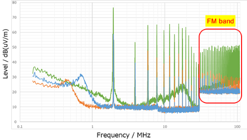
Conclusion
DC-DC converters usually generate large high-frequency noise in the input line as a result of high-speed switching. Therefore, it is especially important to take countermeasures against high-frequency noise, including those in the FM band.
In doing so, it is important to distinguish between normal mode and common mode when implementing noise countermeasures, and appropriate component selection is necessary depending on the noise mode.
Usually, the noise level on the input line of a DC-DC converter is higher in normal mode than in common mode. Therefore, we recommend a π-type filter configuration that is effective for the normal mode.
Additionally, using a three-terminal feedthrough filter for the capacitor used in the π-type filter can further enhance the suppression effect on high-frequency noise.


