Example of ESD Countermeasures on Actual Equipment | LED Protection with Chip Varistors

Table of Contents
What is a Varistor?
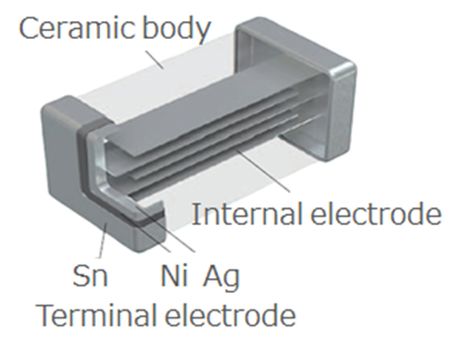
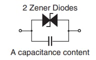
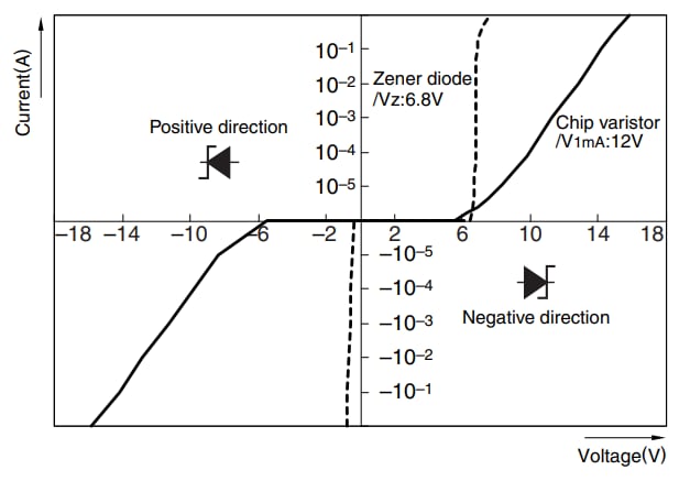
Chip varistors are ceramic semiconductor products based mainly on zinc oxide. As the figure below shows, chip varistors have a laminated structure, with breakdown voltage and capacitance being controlled by the number of layers and the interlayer design. It is a voltage-dependent nonlinear resistive element whose resistance decreases rapidly when a voltage above a certain value is applied. A varistor is equivalent to two series-connected Zener diodes and has no polarity.
●Internal structure of chip varistor
●Equivalent circuit of chip varistor
●Comparison of voltage-current characteristics between chip varistor and Zener diode
Measuring ESD on an Actual Equipment
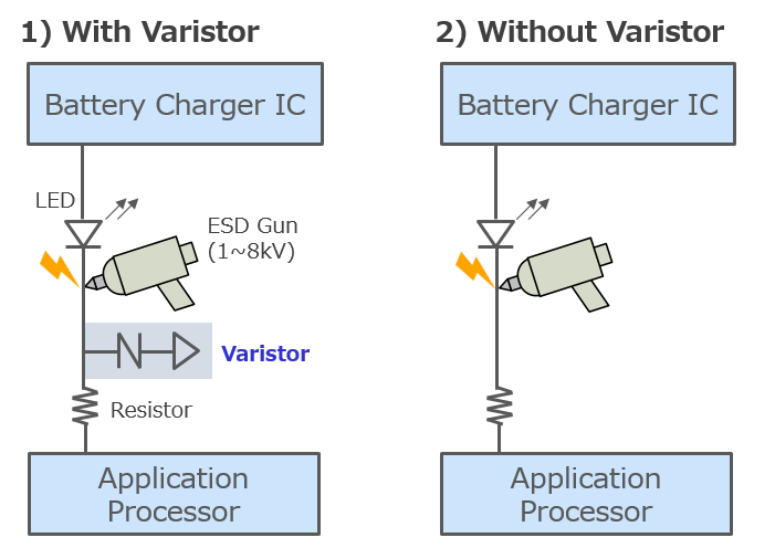
We conducted experiments by mounting an LED on an actual device and checked how the LED light changes as the ESD enters, depending on whether the LED has an ESD protection component (with or without a chip varistor). The application of ESD to the device with mounted LED was performed through electrostatic immunity testing using the human body model (HBM) of IEC61000-4-2, which specifically assumes that charged electrical charges are discharged into electronic devices (see Figures 2 and 3).
ESD Test Conditions
● IEC61000-4-2 (150pF, 330Ω)
● Contact Discharge:1 kV to 8 kV
● ESD Strike Count: 10 at 1 second intervals
Evaluation Results
The table and video show the ESD test results with and without a chip varistor on a device with LED (see Figure 4).
In the presence of a chip varistor, the LED lit up to up to 8 kV ESD discharge.
On the other hand, when an ESD protection element is not used, the LED momentarily turned off at 4 kV to 6 kV ESD discharge. Furthermore, the LED completely turned off at 7 kV ESD discharge.
This result confirms that the LED is affected by ESD. Furthermore, it demonstrated that the chip varistor was capable of protecting the LED from ESD.
| Test Condition | 1kV | 2kV | 3kV | 4kV | 5kV | 6kV | 7kV | 8kV |
|---|---|---|---|---|---|---|---|---|
| 1)With Varistor | (a) | (a) | (a) | (a) | (a) | (a) | (a) | (a) |
| 2)Without Varistor | (a) | (a) | (a) | (b) | (b) | (b) | (c) | - |
The LED kept good condition
up to 8kV using varistor
(a)The LED kept lighting
(Not broken)
(b)The LED went out just for a moment
(about to be broken)
(c)The LED went out
(completely broken)
*The “tik tak” sound indicated the time of applied ESD.
*This particular product has a blinking LED for normal operation and is not due to the application of ESD.
Product Introduction
TDK’s lineup of multilayer chip varistors is mainly for consumer electronics and automotive applications.
For consumer applications, varistors are available in sizes as small as EIA01005 (0.4 x 0.2 mm).
For automotive applications, varistors for mass production come in sizes as small as EIA0402 (1.0 x 0.5 mm).
To summarize, the use of TDK's multilayer chip varistors saves space and allows a high degree of freedom in the mounting layout.
In addition, multilayer chip varistors for automotive applications are available in AEC-Q200, 125°C, and 150°C versions, allowing customers to select a highly reliable and optimal product to suit their applications.
| Size mm [inch] |
Item | Break Down Voltage V1mA [V] |
Maximum Continuous Voltage Vdc [V] |
IEC61000-4-2 (Contact) 150pF/330ohm |
Operating Temperature range [℃] |
AEC-Q200 |
|---|---|---|---|---|---|---|
| 0402 [01005] |
AVRM0402C120MT330N | 12 | 5.5 | 8kV(Level4) | -40 to +85 | |
| 0603 [0201] |
AVRM0603C080MT101N | 8 | 5.5 | 8kV(Level4) | -40 to +85 | |
| AVRM0603C120MT101N | 12 | 5.5 | 8kV(Level4) | -40 to +85 | ||
| 1005 [0402] |
AVR-M1005C080MTAAB | 8 | 5.5 | 8kV(Level4) | -40 to +85 | |
| AVR-M1005C120MTACC | 12 | 7.5 | 8kV(Level4) | -40 to +85 | ||
| B72590D0150H060 (LED) | 23 | 15 | 8kV(Level4) | -40 to +85 | ||
| AVRH10C270KT350NA8 | 27 | 19 | 25kV | -55 to +150 | ✔ | |
| AVRH10C390KT500NA8 | 39 | 28 | 25kV | -55 to +150 | ✔ | |
| B72590D0360B060 | 45 | 36 | 8kV(Level4) | -40 to +85 | ||
| B72590D0201B060 | 600 | 200 | 8kV(Level4) | -40 to +85 | ||
| 1608 [0603] |
AVR-M1608C220KT2AB | 22 | 16 | 25kV | -40 to +125 | ✔ |
| AVRM1608C720KT750M | 72 | 53 | 25kV | -55 to +150 | ✔ | |
| 2012 [0805] |
AVR-M2012C220KT6AB | 22 | 16 | 25kV | -40 to +125 | ✔ |
| AVRM2012C720KT201M | 72 | 53 | 25kV | -55 to +150 | ✔ |


