How to choose a multilayer chip varistor that no failure to surge voltage

In order to solve these problems, we will introduce a simulation tool for multilayer chip varistors that can select the optimal components for countermeasures against surge voltage.
Contents
- Overview video
- Chip varistor/ceramic transient voltage suppressor simulation
- Instructions for Using the Simulation Tool
■Procedure-1 - Enter the peak voltage & pulse width of the surge waveform
■Procedure-2 - Enter the period, number of pulses, and DC voltage of the surge waveform
■Procedure-3 - Create a noise source and varistor circuit
■Procedure-4 - Select the case size and part number of the chip varistor - Simulation Results
■Result-1 - Judgment Result
■Result-2 - Simulation Results
■Result-3 - Surge waveform and output waveform (image)
■Result-4 - Chip varistor current-voltage curve and load voltage & current
■Result-5 - Criteria for determining the pulse derating curve
■Result-6 - Pulse Derating Curve
■Result-7 - Simulation History - Recommended Products List
- Conclusion
- Contact
- Related Links
Overview video
Chip varistor/ceramic transient voltage suppressor simulation
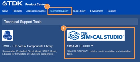
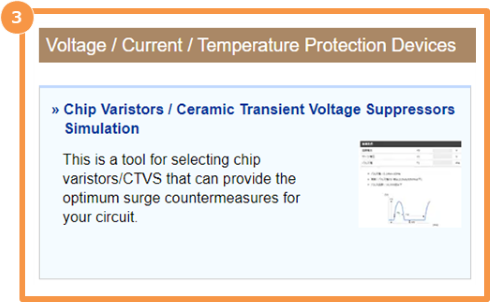
To use the chip varistor/ceramic transient voltage suppressor simulation, please refer to the below web link or (1) technical test, (2) TDK SIM/CAL STUDIO, and (3) Chip varistor/ceramic transient voltage suppressor simulation in voltage/current/temperature protection devices on our HP Product Center site. You can access it more.
-
- » Chip Varistors / Ceramic Transient Voltage Suppressors Simulation
- This is a tool for selecting chip varistors/CTVS that can provide the optimum surge countermeasures for your circuit.
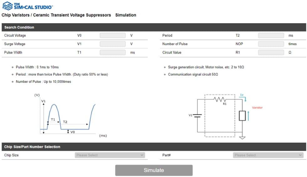
Below is the top screen of the chip varistor/ceramic transient voltage suppressor simulation tool. Let's enter the required information step by step.
Instructions for Using the Simulation Tool
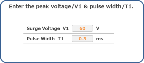
■Procedure-1 - Enter the peak voltage & pulse width of the surge waveform.
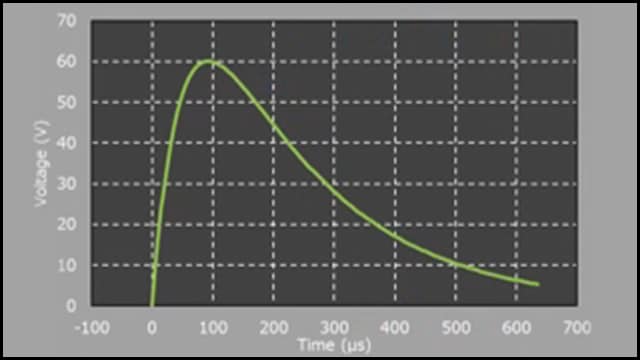
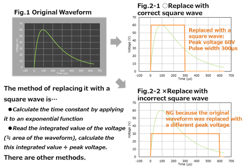
As shown in Figure 1, the surge waveform in problem is obtained and replaced with a square wave.
At that time, the peak voltage is not changed, but the pulse width of the square wave is adjusted.
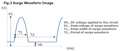
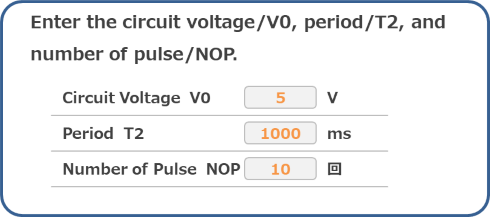
■Procedure-2 - Enter the period, number of pulses, and DC voltage of the surge waveform.
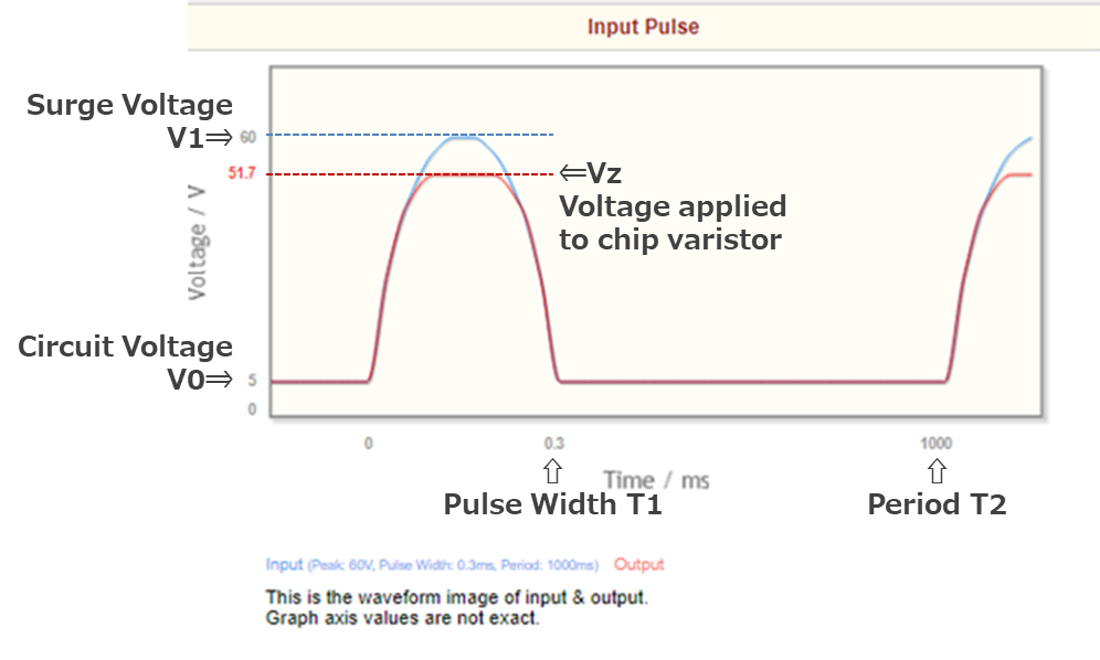
As shown in the surge waveform image in Figure 3, following the peak voltage and pulse width, enter the DC voltage applied to the circuit and the repetition period of the surge waveform.
Also, enter the number of pulses you want to solve.
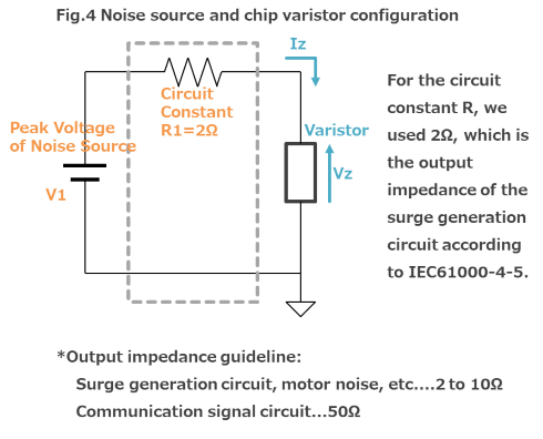
■Procedure-3 - Create a noise source and varistor circuit.
In order to select a product that can handle surge waveforms, the noise source and chip varistor are replaced with a simple circuit.
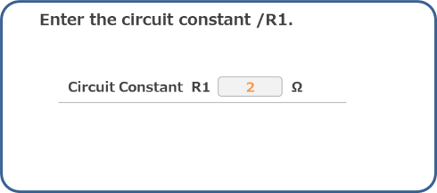
Also set the circuit constant: R (output impedance).
■Procedure-4 - Select the case size and part number of the chip varistor.
Select the "chip size" of the chip varistor that you plan to use for surge protection on your circuit .
Also, from the " Part#" displayed, select the name of the chip varistor product you plan to use.
This completes the entry of the information required for the simulation. Click the "Simulation" button.
6 Simulation Results
■Result-1 - Judgment Result
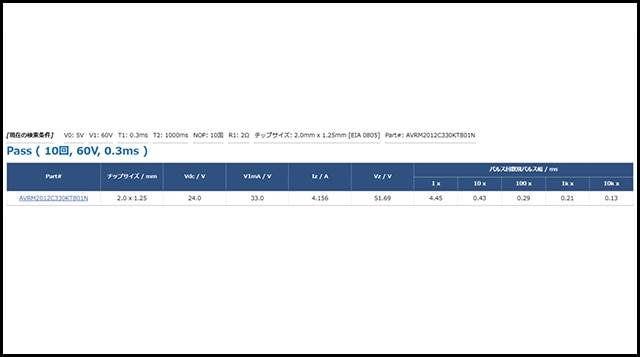
The system displays a determination whether the selected part number supports the surge voltage waveforms that require countermeasures on the customer's circuit.
■Result-2 - Simulation Results
The judgment result also displays the simulation result based on the conditions entered by the customer.
■Result-3 - Surge waveform and output waveform (image)
"Simulation Result: Input Pulse" shows the relationship between the conditions of the surge waveform input by the customer and the voltage (Vz) at which the surge voltage is suppressed by the selected varistor.
Since it is an image diagram, the numerical values of the graph axes are not accurate, but you can capture an image of the entire input and output waveforms.
■Result-4 - Chip varistor current-voltage curve and load voltage & current
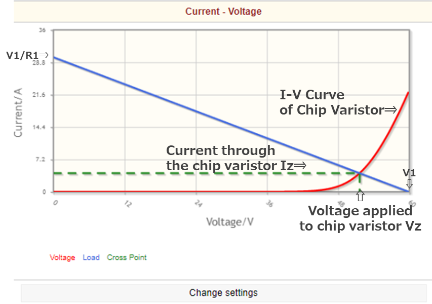
"Simulation Results: Current-Voltage" shows the current-voltage characteristics of the selected varistor and the voltage and current applied to the varistor when the surge waveform is applied.
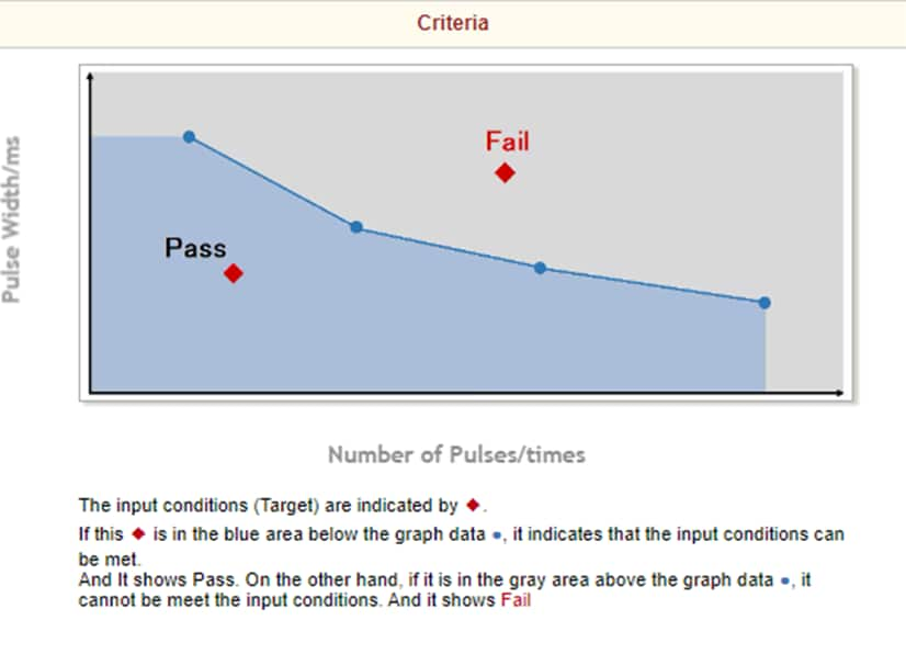
■Result-5 - Criteria for determining the pulse derating curve
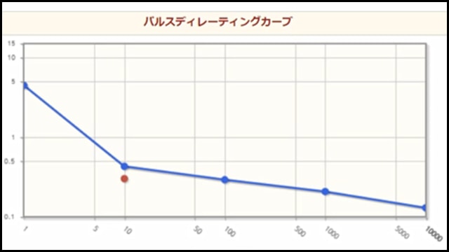
The criteria for "Simulation Results: Pulse Derating Curve" are shown.
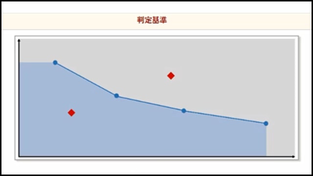
This graph shows the number of pulses applied on the horizontal axis and the pulse width on the vertical axis. The blue data shows the pulse width-number of pulse limit that can be applied to the selected varistor, and the red data shows the conditions of the surge waveform entered by the customer himself.
If the red data is in the blue area below the blue data, the input condition can be handled and Pass is determined.
On the other hand, if it is above the blue data, it cannot be handled and is judged to be Fail.
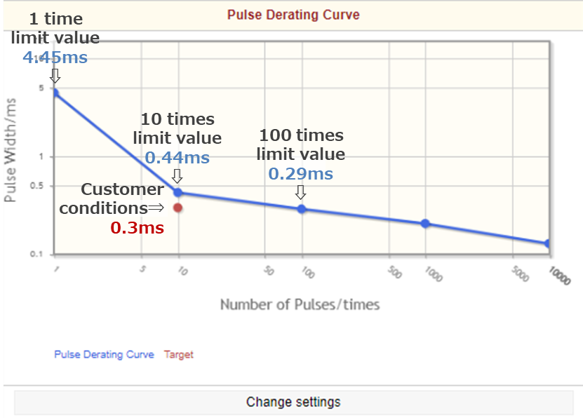
■Result-6 - Pulse Derating Curve
"Simulation Results: Pulse Derating Curve" is shown.
The red data (customer surge conditions) is below the blue data (the limit values for the selected product).
This means that surges in customer conditions can be used without problems when added to the selected product.
Therefore, the judgment result is Pass.
If the red data (customer surge condition) is above the blue data (the selected product limit), it means that the customer condition surge is beyond the product limit and cannot be used. The result is Fail (This part# cannot be supported.) will be.
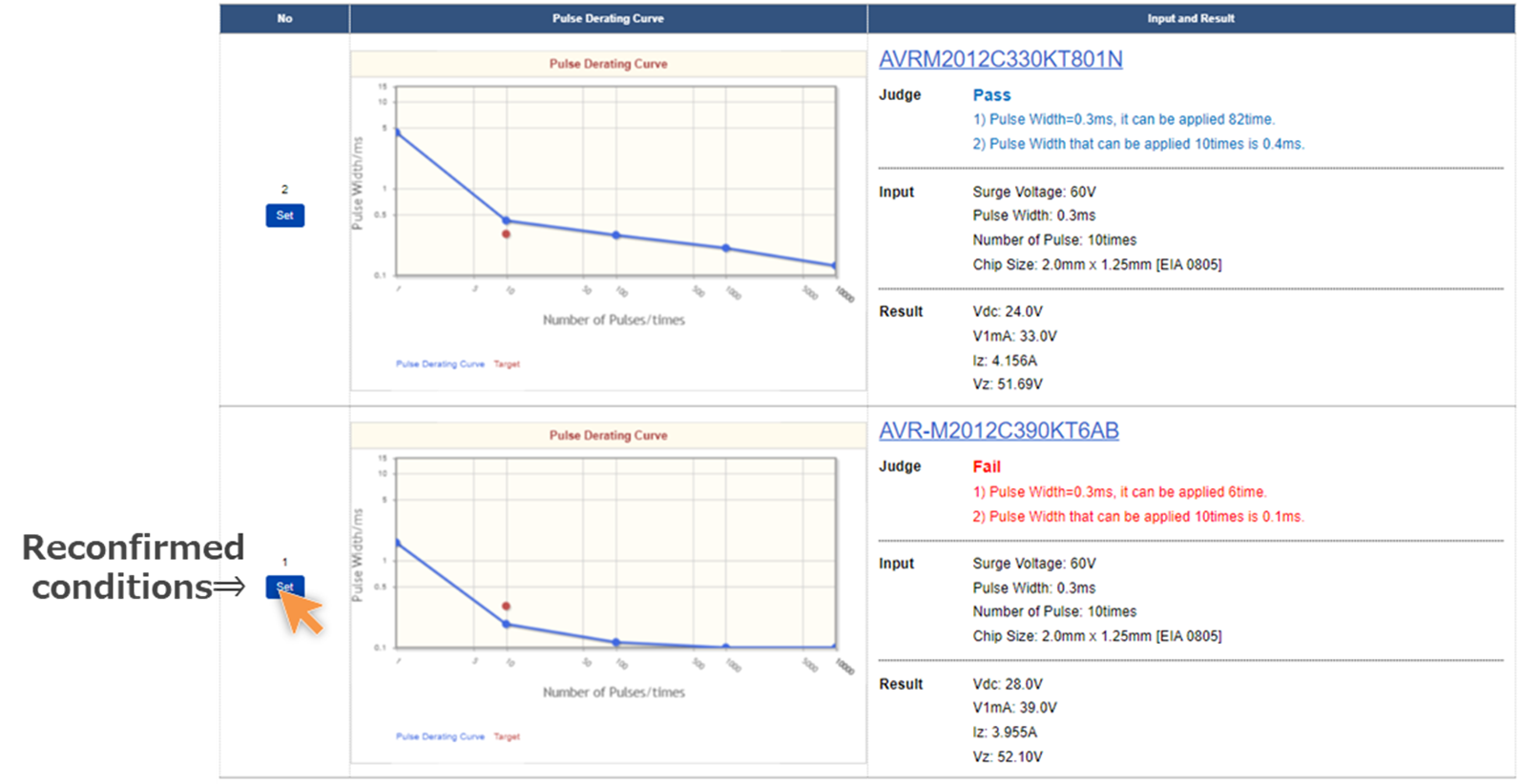
■Result-7 - Simulation History
The simulation results are displayed in history at the bottom.
For the conditions you want to recheck, click the "Refresh" button.
Recommended Product List
For surge countermeasures, we recommend products with high surge current resistance as follows.
If you cannot find a compatible product by the above simulation, please select the following product and try the simulation.
| Part No. | Distributor Inventory | Brand | Apps. | Feature | Apps. Detail | Design | L x W Size |
|---|---|---|---|---|---|---|---|
AVRM1608C270KT221M |
Buy Now | TDK | ≥15kV ESD≥25kV ESDAEC-Q200150°C | LIN/CXPI | 2 Terminal | 1.6mm x 0.8mm [EIA 0603] |
|
AVRM1608C390KT271N |
Buy Now | TDK | ≥15kV ESD≥25kV ESDAEC-Q200150°C | Motor | 2 Terminal | 1.6mm x 0.8mm [EIA 0603] |
|
AVRM2012C330KT801N |
Buy Now | TDK | ≥15kV ESD≥25kV ESDAEC-Q200150°C | Speaker | 2 Terminal | 2.0mm x 1.25mm [EIA 0805] |
|
AVRM2012C560KT251M |
Buy Now | TDK | ≥15kV ESD≥25kV ESDAEC-Q200150°C | 2 Terminal | 2.0mm x 1.25mm [EIA 0805] |
Conclusion
In conventional component selection using individual product data sheets and product catalogs, the following issues have been presented.
- (1) It does not indicate how to read or use the data sheet.
- (2) It is difficult to narrow down the parts that are optimal for countermeasures against surge voltage.
- (3) Spend time on component selection ~ evaluation.
In order to solve these problems, we have created a simulation tool for multilayer chip varistors that can select the optimal components for countermeasures against surge voltages.
By using this simulation tool, you can solve the above problems.
✓ By entering the customer conditions, you can select the product that corresponds to the conditions.
In addition, it is now possible to confirm the following characteristics that could not be determined by the information in the individual product data sheet or product catalog.
✓ It is possible to simulate whether it can respond or not to repeated application of surge waveforms.
✓ You can check the margin against the limit value of the product characteristics.
We hope that you will help you design surge countermeasures for your circuit by using the Chip varistors/ceramic transient voltage suppressors simulation
Contact Information
Related Links
Selection Guide
Application Note
-

- Chip Varistors Prevent Damage of Electronics from Electrostatic Discharge
-

- PCB Layout for ESD Countermeasures | ESD Visualization
-

- How to Use ESD/surge Protection Devices: SMD Varistors
-

- PCB Pattern Design for ESD Countermeasures | ESD Visualization
-

- Example of ESD Countermeasures on Actual Equipment | LED Protection with Chip Varistors

