How to select the right PoC Filter Inductors and Chip Beads for Automotive SerDes (LVDS) Transmission

This article presents examples of the use and effects of PoC filter inductors and chip beads.
What is PoC (Power over Coax)?
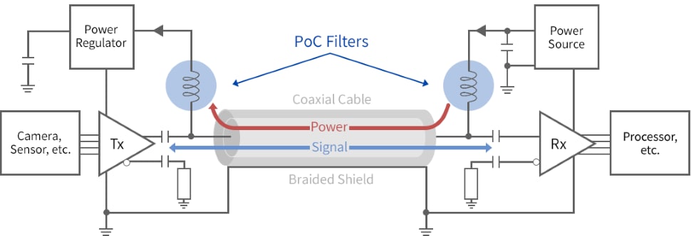
PoC (Power over Coax) is a transmission system that reduces the number of wires by simultaneously transmitting signals and DC power on a single coaxial cable.
In order to separate the DC power supply from the broadband signals, the system is characterized by the use of a DC-cutting capacitor on the signal line side and a filter inductor on the power supply line to prevent the inflow of broadband signals.
There are a number of communication standards led by IC manufacturers and standardization organizations as shown below, and the appropriate inductor must be selected to match the respective signal transmission speed and power supply.
| Standard | Official Name | IC Supplier / Alliance |
| GMSL | Gigabit Multimedia Serial Link | Analog Devices (formerly Maxim Integrated) |
|---|---|---|
| FPD-Link | Flat Panel Display Link | Texas Instruments |
| HSMT | High-Speed Media Transmission | China Local SerDes Supplier |
| ASA-ML | ASA Motion Link | Automotive SerDes Alliance |
| MIPI A-PHY | MIPI A-PHY | Mobile Industry Processor Interface Alliance |
| GVIF | Gigabit Video Inter Face | Sony |
| CLL-BD | Clockless Link-BD | Rohm |
PoC (Power Over Coax) for higher speed and power
Sensing devices such as cameras and radar equipment are becoming increasingly high-capacity, high-functionality, and multifunctional as sensing accuracy improves, requiring higher transmission speeds and more power. As a result, PoC filters are required to support higher transmission speeds, from approximately 1.5 Gbps to 10 Gbps or more, and higher supply power, from 1 W to 5 W.
What is an inductor (coil) optimized for PoC filters?
Space is often restricted in automotive camera modules and other products, requiring miniaturization of the product and reduction of the mounting area. A typical filter consists of four inductors together with chip beads, but constraints can often limit the number of products on the mount. In order to reduce the number of inductors, a product that can maintain impedance frequency characteristics over a wide bandwidth is required. At the same time, this device must maintain its characteristics in high-temperature environments and operate at temperatures up to 150°C.
37% reduction in mounting area
Under the same conditions as the general PoC filter configuration example above, TDK's inductors for PoC filters can be realized with one inductor and two chip beads. This reduces the mounting area by 37%.
| Filter 1 | Filter 2 | Filter 3 | Filter 4 | Rdc[Ω] | Mounting footprint[mm2] |
|
|---|---|---|---|---|---|---|
| Conventional inductor |
NLCV32T-100K-EFRD/2kΩ | NLCV25T-4R7M-EFRD/2kΩ | Chip Beads MPZ1608S102ATD25 |
Chip Beads MMZ1608Y152BTD25 |
2.09 | 24.95 |
-50% |
-37% |
|||||
| Recommended by TDK |
ADL3225VT-100M-TL000 / 1.2kΩ | Chip Beads MPZ1608S102ATD25 |
Chip Beads MMZ1608Y152BTD25 |
Not required | 1.05 | 15.83 |
*Example: 4Gbps 300mA PoC filter
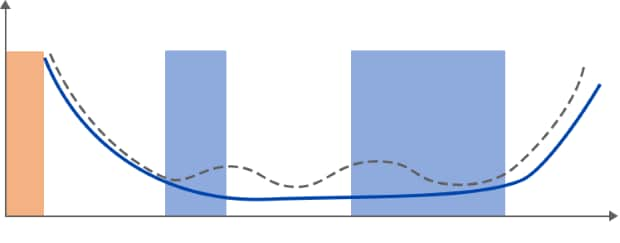
Impedance characteristics maintained over a wide bandwidth
2 to 3 inductors are required for general power circuit inductors.
High ripple due to narrow high impedance bandwidth. TDK's ADL inductor optimized for PoC filter
Low ripple due to wide high-impedance bandwidth
TDK inductors for PoC filters
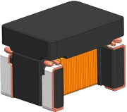
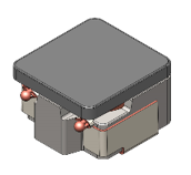
As shown in the diagram (Figure 5) below, TDK offers a wide range of inductors for PoC filters that meet your usage conditions, such as allowable current and filter requirements.(See table below: "TDK inductors for PoC (Power over Coax) filter circuits") The MLJ1608-G series, which is compact and covers a high frequency bandwidth, contributes to a space saving filter design. The ADL series is a product that supports a wide bandwidth, and reduces the overall number of filter coils. As a one-coil solution covering a wider bandwidth, there are the ADL4524VL series and the ADL8030VA series. Additionally, for high current applications, there are the ADL4532VK series and the ADL3225VF series.
* R1 to R3 may vary according to the combination of capacitors and chip beads. Please inquire for details.
TDK inductors for PoC (Power over Coax) filter circuits
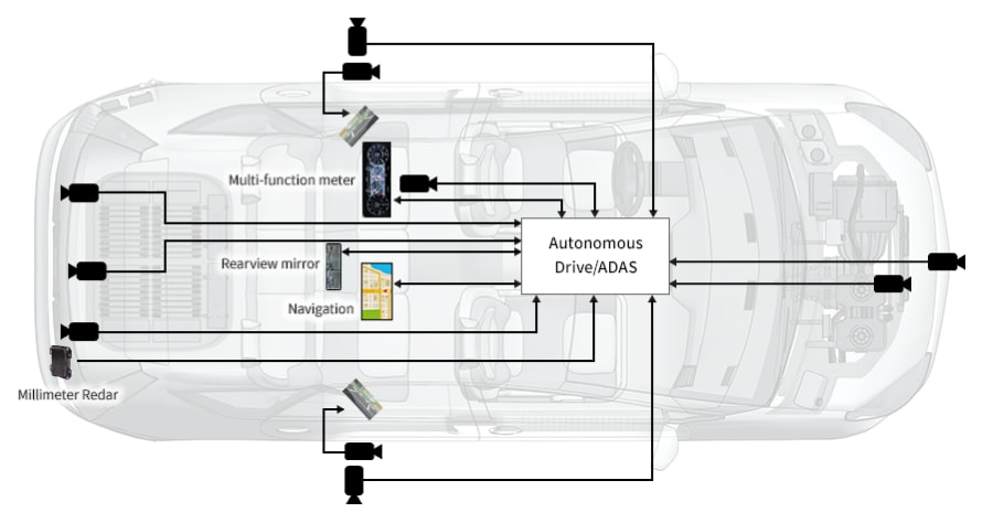
With the increasing speed and sophistication of in-vehicle interfaces, PoC is being promoted in camera systems with SerDes transmission, etc. To separate broadband signals and power in PoC, a wide-band, high-impedance filter using an inductor is required. TDK has a diverse product line-up and can propose filter configurations to suit the current capacity and communication speed of the circuits used.
*Product names in red can be used in 125°C environments.
*The above figures are based on an operating ambient temperature of 105°C. For 125°C environments, the combination may vary, so please contact us for more information.
| PoC current (mA) | 1600 |
|||||||
1400 |
||||||||
1200 |
||||||||
1000 |
||||||||
800 |
||||||||
600 |
||||||||
400 |
||||||||
200 |
||||||||
0 |
0 |
2 |
4 |
6 |
8 |
10 |
12 |
|
| Bitrate (Gbps) | ||||||||
The solution map above is just an example.
We will propose the optimal solution based on your usage environment and requests.
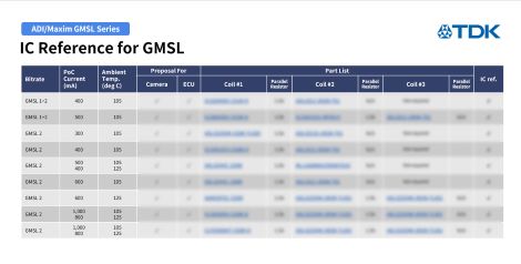
The above PoC filter combinations are examples of TDK products that are used as references by IC manufacturers or filter combinations recommended by TDK. For choosing the best PoC filter combination under other conditions, use the TDK PoC Selection Tool.
List of reference designs
by chipset
