Solution Guide: Replacing Electrolytic Capacitor with MLCC, Revised Guide

Replacing electrolytic capacitors with MLCCs offers various benefits such as space reduction due to smaller size and lower profile, reduced ripple voltage due to low ESR, and improved reliability due to reduced self-heating.
On the other hand, low ESR, which is an advantage of MLCCs, can sometimes lead to abnormal oscillation or anti-resonance. Additionally, high dielectric constant MLCCs (Class 2) exhibit a characteristic capacitance change when DC voltage is applied, so caution is necessary.
This guide explains the advantages and precautions to be taken when replacing electrolytic capacitors with MLCCs.
Table of Contents
- Replacing with MLCCs: Output Capacitor for Step-Down DC-DC Converter
- Main Features of Various Capacitors
- Advantages of Replacing with MLCC
Advantage 1: Reduced space due to smaller size and lower profile
Advantage 2: Reduced self-heating
Advantage 3: Reduced ripple voltage - Is it Effective to Reduce Ripple Voltage by Increasing the Capacitance of Aluminum Electrolytic Capacitors?
- Notes on Replacing with MLCC
Note 1: DC bias (DC voltage applied) characteristics
Note 2: Abnormal oscillation
Note 3: Anti-resonance - Recommended Products for MLCC Replacement
- Product Support
- Summary
Replacing with MLCCs: Output Capacitor for Step-Down DC-DC Converter
Use of low-voltage power supplies has been increasing in recent years as ICs have become more highly integrated. Moreover, the multifunctionality of ICs has led to increased power consumption and higher current consumption. To satisfy these lower voltages and higher currents, distributed power supply systems, which place multiple small DC-DC converters (POL converters) near loads, have been widely used. An example of this would be ICs from an intermediate bus converter.
Multiple capacitors are used in DC-DC converters. In particular, aluminum and tantalum electrolytic capacitors with large capacitance values have been used as output filtering capacitors. However, these electrolytic capacitors are relatively large, making it difficult to reduce space requirements. Furthermore, electrolytics have the disadvantage of high self-heating due to ripple current.
MLCCs effectively overcome these disadvantages through smaller size, lower profile, and lower ESR than electrolytic capacitors.
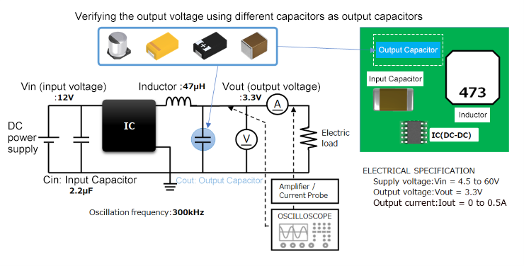
Figure 1 shows the basic circuit of a step-down DC-DC converter, which is widely used in electronic equipment. The output capacitor, shown in blue, is the one that is being replaced from an electrolytic capacitor into an MLCC.
Main Features of Various Capacitors
The main features of typical capacitors, MLCCs, tantalum electrolytic capacitors, and aluminum electrolytic capacitors, are shown below:
| MLCC | Tantalum Electrolytic Capacitor | Aluminum Electrolytic Capacitor | |
|---|---|---|---|
| Advantage | ・Small size/low profile ・Low ESR reduces ripple voltage and self-heating ・Non-polarized |
・High capacitance ・Good DC bias characteristics |
・High capacitance ・Good DC bias characteristics ・Low price |
| Notes | ・Due to its advantageously low ESR, abnormal oscillation or anti-resonance may occur ・Products with high dielectric constant change their capacitance due to DC bias (DC voltage applied) |
・Relatively high ESR ・Relatively high ripple voltage and self-heating |
・Large size ・High ESR ・High ripple voltage and self-heating ・High temperature severely affects product life |
MLCCs offer various advantages such as space reduction due to smaller size and lower profile, reduction of ripple voltage due to lower ESR, and improvement of reliability due to reduced self-heating.
On the other hand, low ESR, which is an advantage of MLCCs, may cause abnormal oscillation or anti-resonance. Additionally, note that MLCCs of high dielectric constant (Class 2) exhibit a characteristic capacitance change with applied DC voltage.
Advantages of Replacing with MLCC
Advantage 1: Reduced space due to smaller size and lower profile
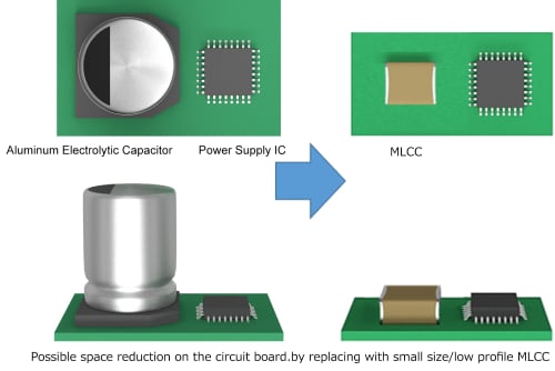
By replacing aluminum electrolytic capacitors with MLCCs, which are smaller and have a lower profile, space on the circuit board can be reduced.
Advantage 2: Reduced self-heating
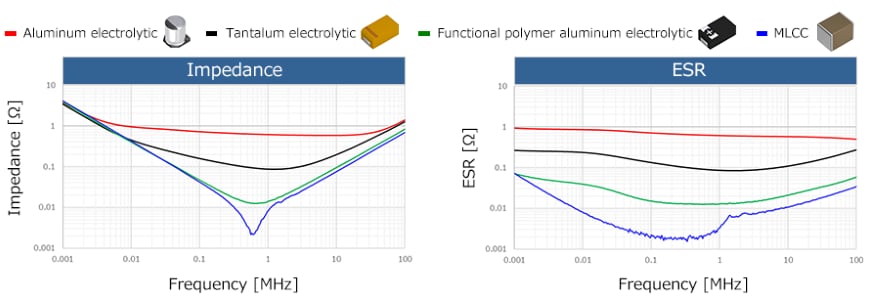
The figure initially shows the impedance and ESR frequency characteristics for 47 μF MLCC, aluminum electrolytic capacitor, tantalum electrolytic capacitor, and functional polymer aluminum electrolytic capacitor.
MLCC exhibits low characteristic values for both impedance and ESR.
The self-heating value of the capacitor (P) is expressed by the following equation based on the ESR of the capacitor and the ripple current (I).
Self-Heating Rate: P = ESR x Current: I2 (Equation 1)
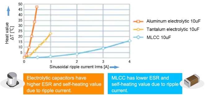
Since self-heating value (P) is directly proportional to ESR, MLCCs exhibit much less temperature rise than the higher ESR aluminum/tantalum electrolytic capacitors.
The product life of a capacitor is affected by temperature. Generally, through what is known as the "10°C 2-fold rule", for every 10°C rise in operating temperature, the product life will be cut in half. This means that a high self-heating value due to ripple current will shorten the product life. The typical product life of an aluminum electrolytic capacitor is about 10 years.
Advantage 3: Reduced ripple
・Verifying output voltage of step-down DC-DC converters
The output voltage of a step-down DC-DC converter was measured using the following testing system:
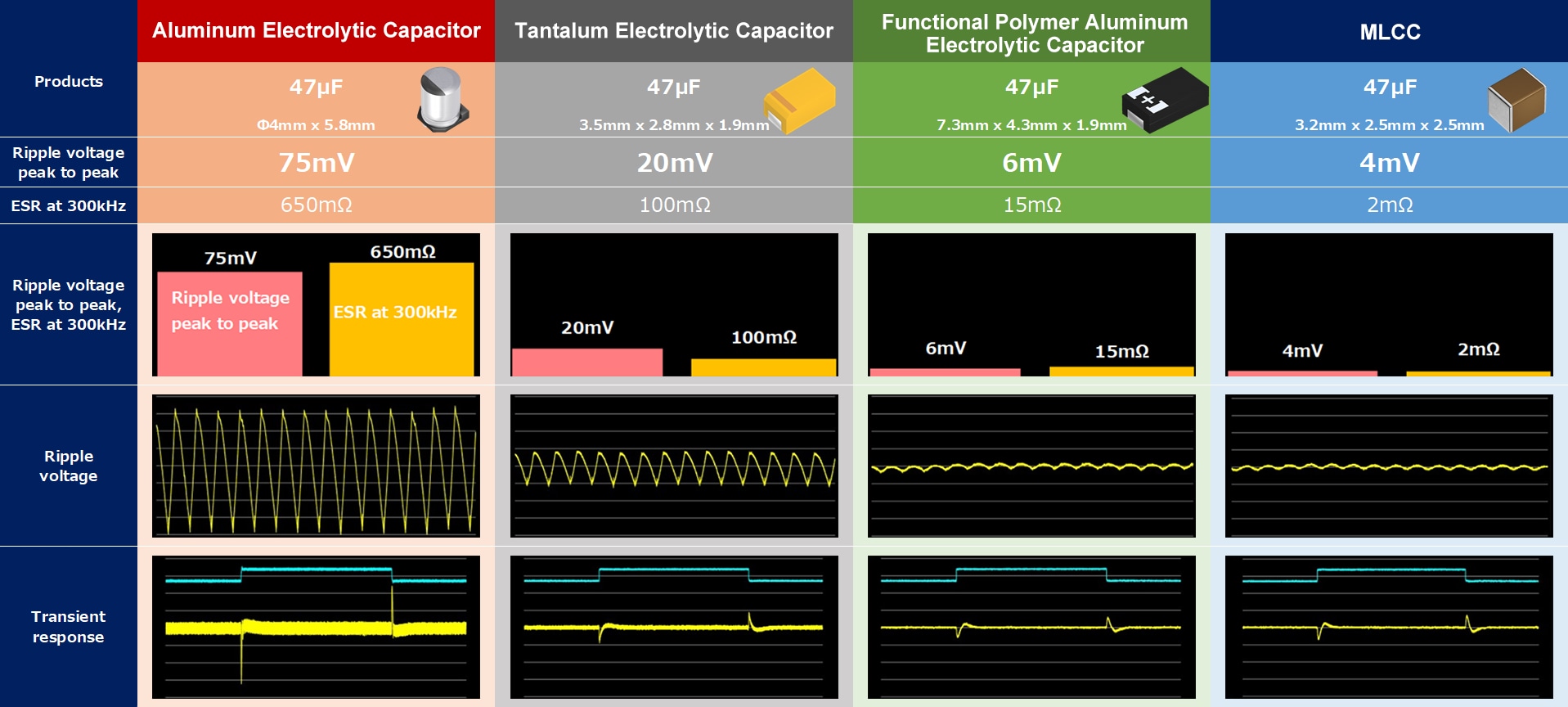
A 47μF MLCC, aluminum electrolytic capacitor, tantalum electrolytic capacitor, and functional polymer aluminum electrolytic capacitor were used as output capacitors.
The figure shows the output voltage waveform and ESR for each type of capacitor at a typical oscillation frequency of 300kHz.
Both ripple voltage and ESR are lowest for the MLCC type.
The relationship between ripple voltage and ESR is expressed by the equation below. It can be seen that reducing ESR effectively reduces ripple voltage, and therefore, MLCC, which has a low ESR, is advantageous.
Functional polymer aluminum electrolytic capacitors use conductive polymers as electrolytes to reduce ESR, resulting in lower ripple voltage compared to general aluminum electrolytic capacitors, but they are generally slightly larger in size and more expensive.
Is it Effective to Reduce Ripple Voltage by Increasing the Capacitance of Aluminum Electrolytic Capacitors?
We evaluated the relationship between the capacitance of aluminum electrolytic capacitors and ripple voltage.
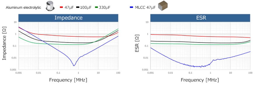
First, the figure shows the impedance and ESR frequency characteristics of MLCC at 47μF and general aluminum electrolytic capacitors at 47μF, 100μF, and 330μF.
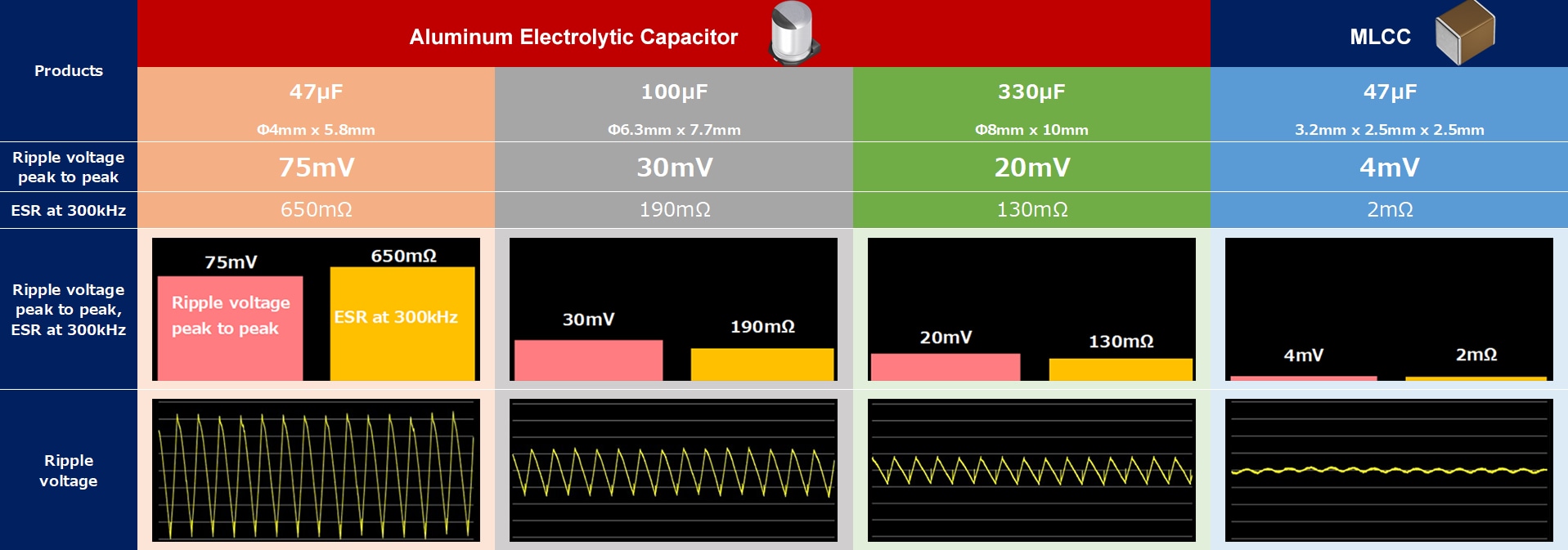
Additionally, using the same testing system in Figure 5, we measured the output voltage of a step-down DC-DC converter using an MLCC at 47μF and aluminum electrolytic capacitors at 47μF, 100μF, and 330μF as output capacitors.
The figure shows the output voltage waveform and ESR for each type of capacitor at a typical switching frequency of 300kHz. As the capacitance of the aluminum electrolytic capacitor increases, the ripple voltage decreases, but the decrease is relatively small.
Considering the reason for this in Equation 2, the increase in capacitance reduces the ripple voltage, but its effect is considered to be smaller than that of ESR.
Therefore, it is difficult to effectively reduce the ripple voltage by increasing the capacitance of aluminum electrolytic capacitors.
Notes on Replacing with MLCC
When replacing electrolytic capacitors with MLCCs, take note of the following factors: DC bias (DC voltage applied) characteristics, abnormal oscillation, and anti-resonance.
Note 1: DC bias (DC voltage applied) characteristics
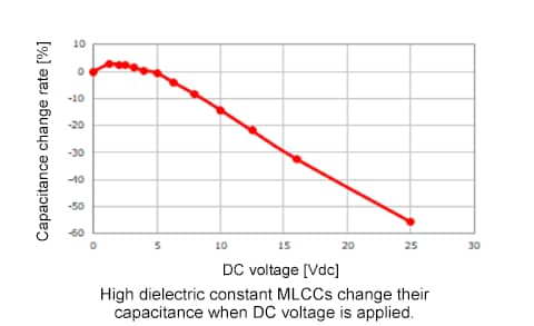
MLCCs of high dielectric constant (Class 2) have a characteristic of capacitance change when DC voltage is applied, and this characteristic is called the DC bias (DC voltage applied) characteristic.
Therefore, DC bias characteristics should be considered when using MLCCs with DC voltage applied.
Note 2: Abnormal oscillation
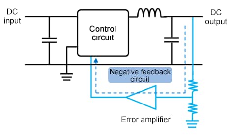
Low ESR, which is an advantage of MLCC, can sometimes cause unstable output voltage or abnormal oscillation of the DC-DC converter. The DC-DC converter obtains a constant and stable DC voltage by comparing the output voltage to a reference voltage, amplifying the error difference by an error amplifier, and feeding it back negatively.
During this process, a phase delay is generated by the smoothing circuit's inductor and capacitor. When the phase delay approaches 180°, it becomes like a positive feedback, leading to unstable output voltage or abnormal oscillation.
・Prevent abnormal oscillation through Phase Compensation
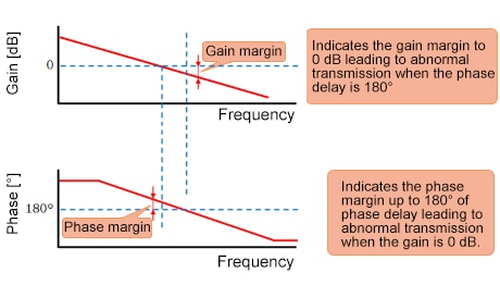
A Bode Plot is a method of determining whether negative feedback operates stably. The Bode Plot is a graph with frequency on the x-axis and gain and phase on the y-axis.
As the phase delay due to the inductor and capacitor approaches 180°, positive feedback occurs and the output becomes unstable. On the other hand, even when the phase delay is 180°, it is possible to prevent signal convergence and abnormal oscillation by keeping the gain below 1 (less than 0dB).
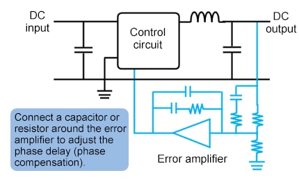
Therefore, to reduce the phase delay, a capacitor or resistor is connected around the error amplifier to cancel the phase delay. This is called phase compensation.
While this is not a problem with conventional designs using aluminum electrolytic capacitors with high ESR for the output capacitor, care should be taken because low ESR MLCCs may cause insufficient phase compensation, leading to abnormal oscillation.
You may also refer to another article, "MLCC Solutions for Power Supply Circuits (Verification of Optimal Structures for Output Capacitors)".
Note 3: Anti-resonance
Furthermore, care must be taken when using low ESR MLCCs for decoupling purposes.
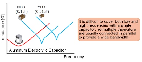
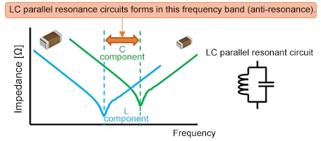
Generally, multiple capacitors are connected in parallel as decoupling capacitors for ICs operating at high currents and low voltages. For decoupling purposes, capacitors with low impedance over a wide frequency range are ideal, but the impedance frequency characteristics of MLCCs exhibit a V-shaped behavior.
The frequency at the bottom of the V is called the self-resonant frequency (SRF). When MLCCs with different SRFs are mounted in parallel, an LC parallel resonant circuit is formed by the capacitance and parasitic inductance component of the MLCCs. This phenomenon is called anti-resonance.
Anti-resonance causes intense impedance peaks, which reduces noise rejection at that frequency. As a result, the supply voltage can become unstable and circuit malfunctions may occur.
Recommended Products for MLCC Replacement
You can check our recommended TDK MLCC products by selecting the type of electrolytic capacitor you are using.
*This does not guarantee product compatibility. Please check the compatibility of the product before use.
Recommendations for replacing electrolytic capacitors with MLCCs (PDF)
Just click to see the recommended replacements.
Product Support
TDK offers free design support tools. Please utilize them for circuit design and EMC measures.
Summary
With increasing capacitance values, MLCCs are replacing various electrolytic capacitors in power circuits and other applications.
Replacing electrolytic capacitors with MLCCs offers various benefits such as space reduction due to smaller size and lower profile, reduced ripple voltage due to low ESR, and improved reliability due to reduced self-heating.
On the other hand, low ESR, which is an advantage of MLCCs, can sometimes lead to abnormal oscillation or anti-resonance. Additionally, high dielectric constant MLCCs (Class 2) exhibit a characteristic capacitance change when DC voltage is applied, so caution is necessary.
TDK offers an extensive lineup of MLCCs and supports the replacement of various electrolytic capacitors. Please select the MLCC that best fits your application to improve your product reliability.


