Flex Crack Countermeasures in MLCCs Vol.1
TDK offers five series of high-reliability MLCC products which are designed to reduce the risk of flexure stress related to short circuit in order to improve equipment reliability. Vol.1 of this guide introduces three series using soft termination electrodes. Please select suitable products from these series and use them to improve the reliability of your equipment.
 Contact Us
Countermeasures for flexure crack: Five high-reliability MLCCs series
TDK offers solutions for a wide range of products.


Major causes of flexure cracks and influence on reliability
One of the major reasons of ceramic element cracks in MLCCs is due to board flexure stress occurred by a variety of reasons.
- Handling during manufacture: Stresses by suction nozzle, inappropriate solder amount, different thermal expansion between MLCC and board, board splitting, screw cramp and excessive board bending, etc.
- Handling in use: Stresses by drop shock and vibration, etc.
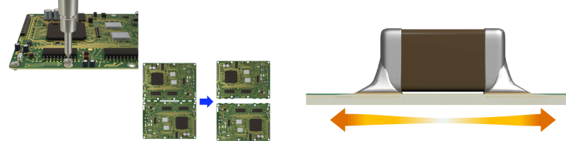
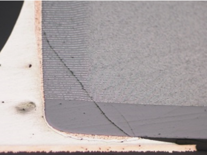
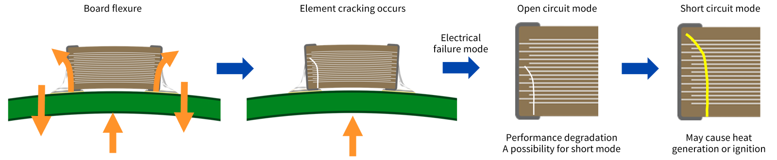
Ceramic elements are strong against compression stress, though weak against tensile stress, thus, a crack is easily generated in the element when excessive stress is acting on a soldered MLCC from the board direction. Then, a short circuit failure mode occurs if electrical conduction happens between opposite internal electrodes.
Even if there is an open circuit mode at the beginning of the crack occurrence, it may progress to a short circuit mode while the product is on the market. The short circuit mode may cause problems such as abnormal heat generation or ignition of the MLCC, and so suitable countermeasures are required.
Board flexure
- Suction nozzle stress
- Inappropriate solder amount
- Board splitting
- Excessive board flexure, etc.
Applications which flexure crack countermeasures are effective
There is a risk that microcracks occurring in the various processes from component mounting to set assembly will progress to ceramic element cracks while the end product is on the market. Special caution is required especially in case of the following applications.
- Equipment which is constantly exposed to vibrations and/or shocks: equipment of automobiles, railway vehicles and industry, etc.
- Equipment which is exposed to frequent shock by dropping: mobile devices and smart key, etc.
Furthermore, with the equipment used in a humid environment, moisture by condensation may penetrate into the element crack, thereby the risk which open circuit mode progresses to a short circuit mode increases.
Applications which flexure crack countermeasures are effective
| Usage environment | Application | |
|---|---|---|
| Equipment which is constantly exposed to vibrations and/or shocks | Automotive electronics, Industrial equipment, Railway equipment | Click here for Application Guides |
| Equipment which is exposed to frequent shock by dropping | Smart Phones, Smart Watches, Smart Keys | |
| Equipment used in a humid environment | Automotive electronics, Industrial equipment |
Soft termination
In a test with a substrate bending amount of 10 mm, the body crack occurrence rate was 100% for standard-terminal products, compared to 0% for resin electrode products. These results demonstrate that resin electrode products relieve the stress generated by board flexing, thereby reducing the risk of body cracking in MLCCs.
Note: The test conditions are as shown in the figure on the right.
No element cracks were observed even after board was flexed up to 10mm
In a test with a substrate bending amount of 10 mm, the body crack occurrence rate was 100% for standard-terminal products, compared to 0% for resin electrode products. These results demonstrate that resin electrode products relieve the stress generated by board flexing, thereby reducing the risk of body cracking in MLCCs.
Note: The test conditions are as shown in the figure on the right.

Suppression of element crack occurrence by resin electrode peeling
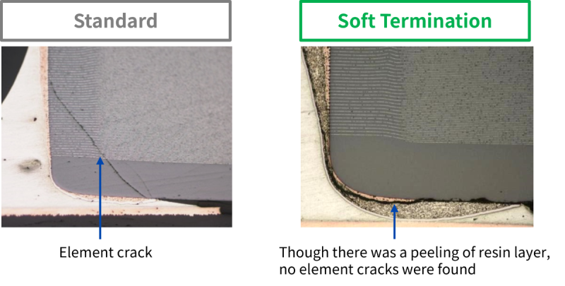
When excessive stress was continuously applied, cracks occurred in the ceramics element in a standard product. In contrast, with the soft termination product, no cracks were found in the element, though there was a peeling of the nickel layer and the resin layer. This shows that the resin layer has an excellent effect to suppress element cracks.
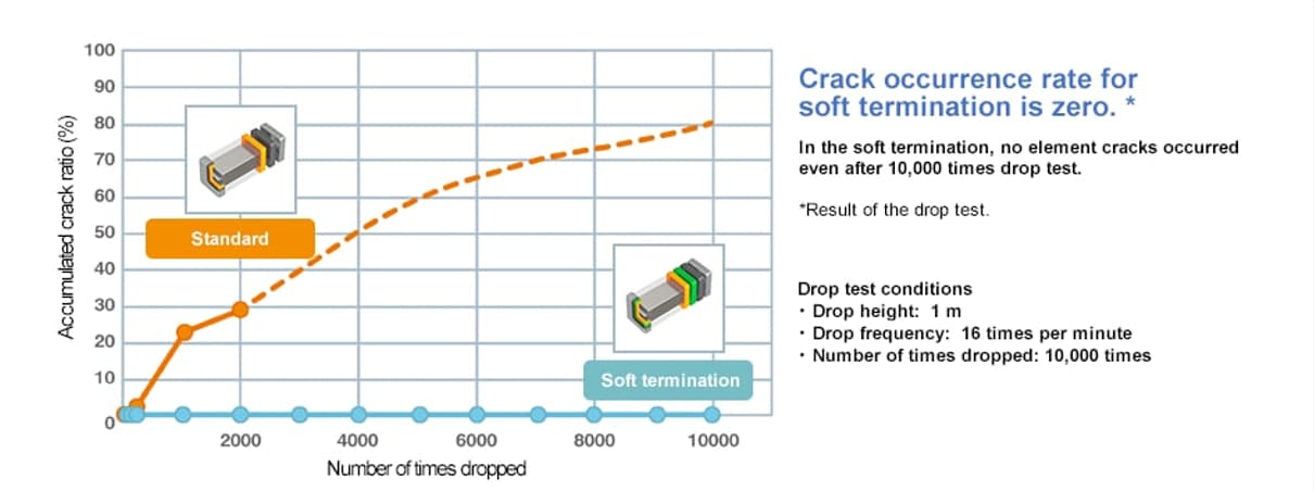
No crack occurred even after 10,000 times drop test (*not a guaranteed item)
The drop test was performed assuming mobile applications. In the soft termination product, no cracks occurred even after 10,000 times drop test, thereby this shows that the resin electrode relieved the shock.
【Advantages of soft termination】
- High resistance to mechanical stress and thermal shock by resin layers
- X8R and X8L type whose maximum temperature are up to 150°C are available
- C0G type having excellent stable temperature and DC-bias characteristics is also available
【Major applications】
- Fail-safe design for battery line
- Prevention of ceramic element crack by board bending
- Prevention of solder crack by thermal shock
- Equipment such as mobile devices and smart key having a high possibility of drop

Soft termination (low resistance type)
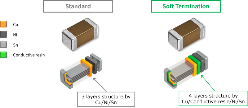
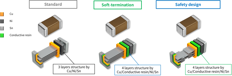
Soft termination MLCCs have a conductive resin layer within the terminals to provide mechanical stress relief, however, the layer has additional resistance including the ESR characteristic. With the aim of suppressing this disadvantage, new type of soft termination product with original terminal structure has been developed. The material constituents of terminal are the same as conventional soft termination, however, the resin layer is applied to the board mounted side only.
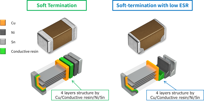
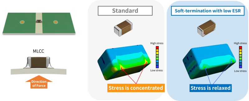
Effective stress relief by applying the resin layer to the board mounted side only
The purpose of this design is explained from a viewpoint of board flexure stress. The mechanical stress by board bending primarily concentrates at the bottom of the terminals on the board mounted side. Low resistance type provides effective stress relief by applying the resin layer to the risk area only, not to whole area of the terminal.
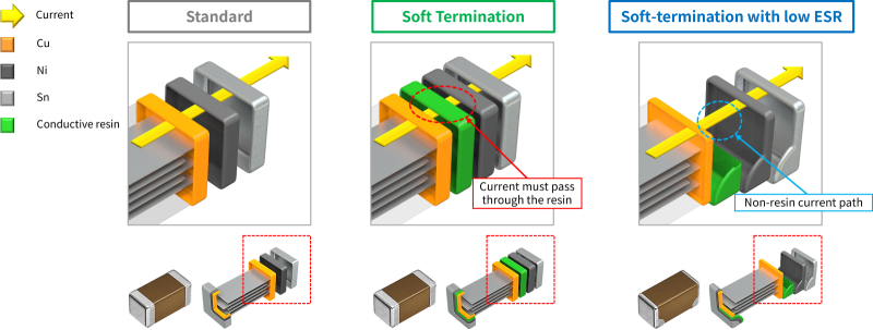
Current passing through terminal electrode
The advantages of this structure are described due to the difference in current path passing through the terminal. In case of the conventional soft termination products, the entire surface of terminal is covered with the resin, so electric current must pass through the resin layer. Because the layer has a higher resistance than metals such as copper, the total resistance is slightly higher than that of standard type products. In contrast, the new design allows the current to pass outside the resin layer. Therefore, the resistance rise is suppressed at the same level as the standard type.
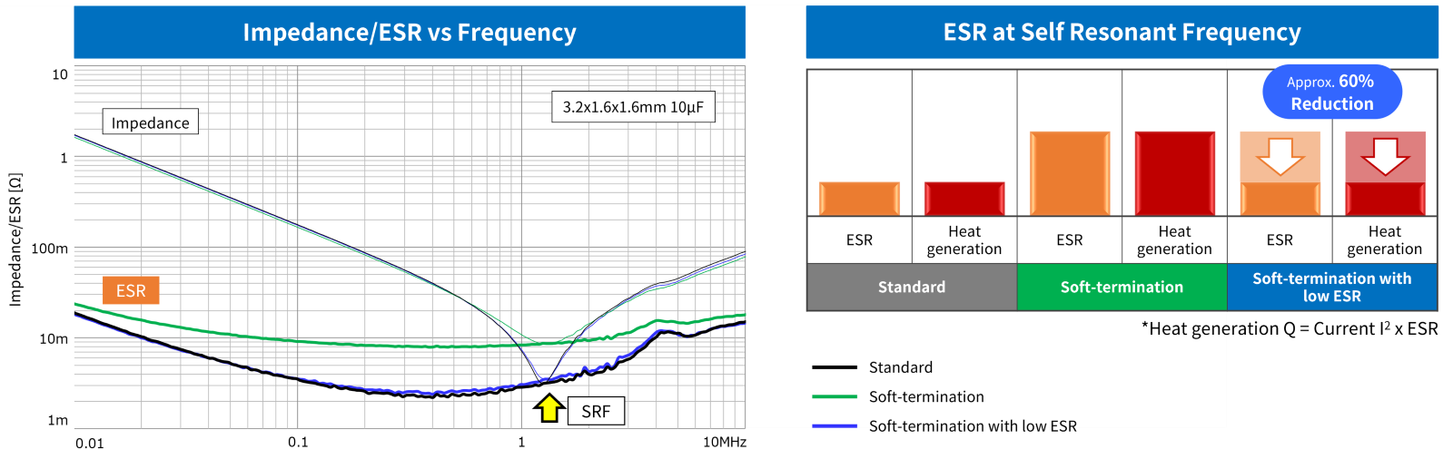
Reduction in Impedance/ESR
The effect is shown in the impedance/ESR frequency characteristics. The resistance value of the conventional soft termination (green) is higher than standard type(black), while low resistance type (blue) shows the same level as standard type. At the self resonant frequency (SRF), the ESR of the low resistance type is approximately 60% lower than the conventional soft termination type, and a similar reduction in heat generation can be expected (heat value is proportional to ESR). Furthermore, keeping a similar impedance and ESR reduces the risk of switching from standard type to soft termination type, the shift to soft termination may be encouraged.
Board flexure resistance: Same level as conventional soft termination product
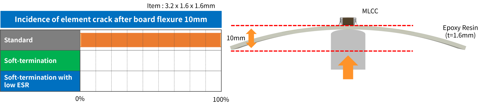
Next, the results of the board flexure test is shown. In case of soft termination product, no element cracks were observed in both conventional and low resistance type even after the board was flexed up to 10mm. From the results, it is clear that low resistance type has realized both the board flexure resistance and low electric resistance.
【Advantage of low resistance soft termination】
- Because the current can pass outside the higher resistance path due to applying the resin layer to the board mounted side only, low electric resistance has been realized.
【Major applications】
- Fail-safe design for battery line
- Prevention of ceramic element cracks by board bending
Safety design
Safety design type is a product which has two capacitor structures in series in a single body.
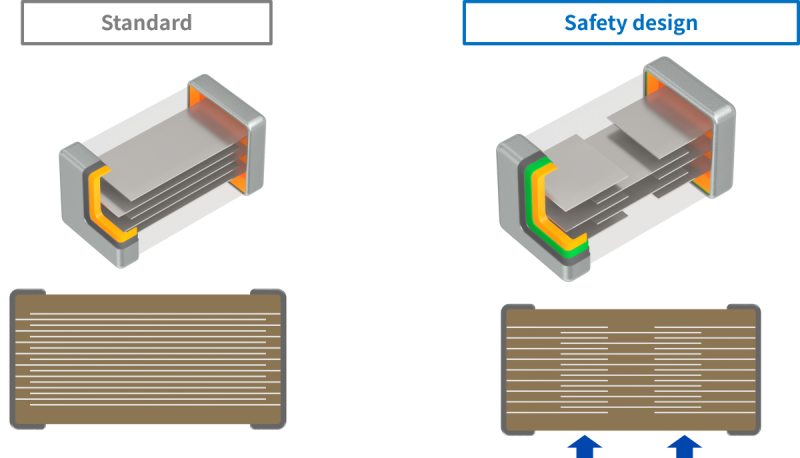
| General structure which opposite inner electrodes are alternately stacked | Structure which has two capacitors in series in a single body (serial design) |
Advantages of serial design
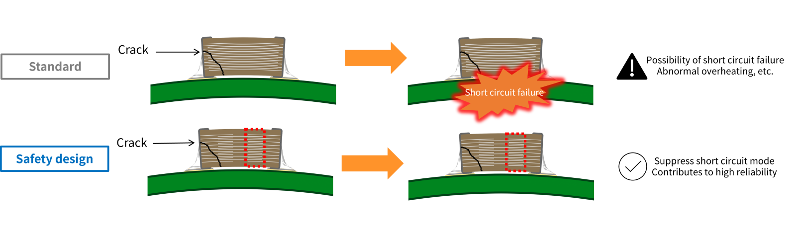
In standard products, when a crack occurs in the MLCC, the crack penetrates the internal electrode layers, which can lead to a short-circuit failure between internal electrodes.
In contrast, in safety-design products, even if a crack occurs in the capacitor structure on the left side, the series-connected dual-capacitor structure allows the capacitor structure on the right side to remain intact, thereby suppressing the occurrence of a short circuit. (See Figure 13)
Adoption of soft termination
Additionally, safety design product as well as soft termination product has high resistance to mechanical stress and thermal shock by resin layers. Thus, safety design product is an outstanding high reliability product.
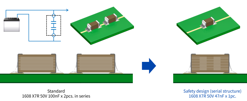
Example of replacement with safety design product
Two capacitors are often mounted in series to decrease the risk of short circuit caused by cracks in battery line. With the safety design product, the serial design in a component acts as the prevention function, therefore the product will contribute to reduce the number of MLCCs.
【Advantages of safety design】
- Serial structure decreases risk of short failures by crack
- High resistance to mechanical stress and thermal shock by resin layers
【Major applications】
- Fail-safe design for battery line
- Circuits requiring safer design


Related Links