Temperature sensing of LED Flash with NTC thermistor

By mounting the NTC thermistor in close proximity to the heat source, it can accurately sense the temperature of the heat source. However, in some cases, such as when there are constraints on the size of the board or the pattern layout, it may need to be mounted in a location away from the heat source.
In this article, considering such conditions, we used the LEDs on the LED flash circuit board as the heat source and simulated heat generation to check the temperature difference between the LEDs and the NTC thermistors caused by the different mounting positions. We also checked the effect of circuit board thickness.
Table of Contents
Objective
By mounting the NTC thermistor in a position closer to the heat source, it is possible to sense the temperature of the heat source accurately.
However, there are cases where the NTC thermistor must be mounted at a distance away from the heat source due to constraints such as board size and pattern layout.
In case of the LED module in the LED flash board as the heat source, we checked the temperature difference caused by the difference in the mounting positions of the LED and NTC thermistor using a heat generation simulation software (PICLS - Provided by Software Cradle Co., Ltd.). We also checked the effect of board thickness.
Target Set
Create a simulation model of the circuit board based on the design of a LED flash board for smartphones.
- Circuit board dimensions:6.5 x 5.0mm
- LED Dimensions:1.0 x 1.0mm
- LED Output:30mW x 4 pieces
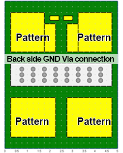
●Circuit board outline and Component layout
●Front side of the circuit board
●Back side of the circuit board
●Circuit board design
✔ Dimensions: 6.5 x 5.0mm
✔ Double-sided circuit board: (FR4 board)
✔ Substrate thermal conductivity: 0.25W/mk
✔ Pattern (Cu) thickness: 35μm
✔ Cu thermal conductivity: 398W/mk
Simulation Conditions
Below are the conditions for the simulation.
Condition 1: Circuit board thickness
In the LED flash board, the GND pattern on the front side is connected to the back side through via.
Main material of the circuit board is FR4.
The thicker the circuit board, the more FR4 material is used.
We set the board thickness to two cases: 0.4mm and 1.6mm.
Condition 2: NTC thermistor mounting position
Four 1mm-sized LEDs are mounted in the center of the LED flash board.
EIA01005(0.4x0.2mm) NTC thermistor are placed at a distance away from the LEDs.
The NTC thermistors are mounted at a distance of 0.25mm, 1.00mm, and 1.75mm from the LEDs.
Temperature Measurement Points
During heat generation simulation, we set four temperature measurement points on the surface of the LED and the NTC thermistor.
Simulation Results
Result 1: 0.4mm board thickness
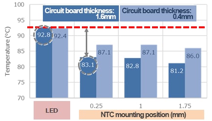
The LED surface temperature reached 92.5℃.
The NTC thermistor surface temperature decreased as the distance from the LED became farther.
There was a temperature difference between the surface temperature of the NTC thermistor and the LED.
There was a temperature distribution on the circuit board surface, and a temperature difference also occurred between the conductor pattern and FR4.
- ■Condition 1: Circuit board thickness
- 0.4mm
- 1.6mm
Result 2: 1.6mm board thickness
The LED surface temperature reached 92.8℃.
The NTC thermistor surface temperature decreased as the distance from the LED became farther.
There was a temperature difference between the surface temperature of the NTC thermistor and the LED.
There was a temperature distribution on the circuit board surface, and a temperature difference also occurred between the conductor pattern and FR4.
- ■Condition 1: Circuit board thickness
- 0.4mm
- 1.6mm
Summary of heat generation simulation results
Temperature difference depending on the NTC thermistor mounting position:
It difficult for heat from the LED to be transferred to the surrounding area, because FR4 has low thermal conductivity like 0.25W/mk.
The result of this simulation has the temperature difference between the LED and the surrounding area.
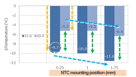
The temperature difference between the LED and the NTC thermistor increases as the distance from the LED becomes farther.
Conclusion on the effect of board thickness:
The results for boards of different thicknesses show that thicker board lead to increased temperature differences between the LED and the NTC thermistor.
Δtemperature:
Indicates the difference between the surface temperature of the NTC thermistor and the LED.
Example:
83.1-92.8= -9.7℃
Temperature Sensing Circuit Using NTC Thermistors
In case of the circuit board material with FR4, the heat from the heat source does not expand easily to the surrounding area.
Then, there is the temperature difference between the LED and the surrounding area.
In addition, the further away from the heat source, the big temperature difference between the heat source and the NTC mounting position.
When designing a temperature sensing circuit, these phenomena need to be taken into consideration.
Component Selection Procedure
To ensure that the LED surface temperature does not exceed 90°C during temperature sensing, please follow these guidelines:
1. Consider the location of the heat source (LED) on the board.
2. Consider the mounting location of the NTC thermistor.
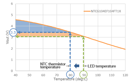
3. Check the surface temperature of the LED and the NTC thermistor in each mounting position. (Assume that the NTC temperature is 80°C when the LED temperature is 90°C)
4. Select a sensing circuit that provides high-precision output characteristics at 80°C.
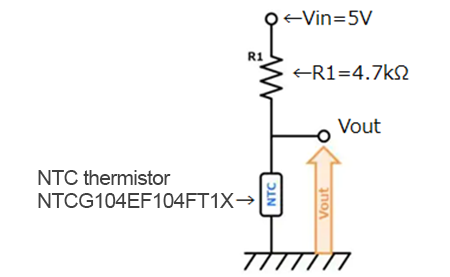
■Sensing Circuit
■Output Voltage(Vout) Characteristic
NTC temperature: Check the output voltage (Vout) at 80℃.
If Vout reaches 3.5V or higher at this point, the LED temperature is maintained at 90℃ or below.
Summary
It has the temperature difference between the heat source and the surrounding area, because FR4 has low thermal conductivity like 0.25W/mk.
The temperature difference between the heat source and the NTC thermistor increases as the distance from the heat source becomes farther.
By checking the temperature at the NTC mounting position and selecting a sensing circuit that ensures high-precision output characteristics, an optimal circuit using an NTC thermistor can be constructed.
The recommended NTC thermistor part numbers for general-use LED flashes (consumer grade) and LED headlights (automotive grade) are shown below.
■Recommended Part Number
| Application | TDK Part No. |
Case Size | Resistance at 25℃ | B Value 25/85℃ |
|---|---|---|---|---|
| LED Flash (Consumer Grade) |
NTCG044EF104FTBCX | 0402mm | 100kΩ | 4293K |
| NTCG064EF104FTBX | 0603mm | 100kΩ | 4308K | |
| LED Headlight (Automotive Grade) |
NTCG104EF104FTDSX | 1005mm | 100kΩ | 4308K |
| NTCG164KF104FTDS | 1608mm | 100kΩ | 4485K |
In addition, when selecting sensing circuits and NTC thermistors, please make use of the NTC thermistor simulation tool available on the TDK website.


