Single Pair Ethernet: How to implement 10Base-T1L

In addition, the number of nodes in networks are constantly increasing therefore the desire to use an existing ecosystem is strong. Ethernet protocol and security layers as well as well-known installation, maintenance and management processes result in a lower Total Cost of Ownership (TCO) and a better Return on Investment (ROI) in the Network.
Industrial applications focus on a network speed of 10 Mbps as this should address the data rate and reach for most of the existing fieldbus applications. TDK offers an extensive lineup of various inductors for use in 10Base-T1L applications including common-mode chokes (CMCs), isolation inductors (Isolated Coupled Inductors) and differential mode inductors (DMIs).
Contents
Definition and Standards
Industrial Ethernet can easily be mixed up with regular Ethernet in industrial applications and will sometimes be called Single Pair Ethernet (SPE). This architecture is derived from standards known in classic LAN applications where two or four twisted pairs of wires are used to transmit data with either 100 Mbps (Megabit per second) or 1000 Mbps. SPE is using only one twisted pair of cables and is used for communication speeds ranging from 10 Mbps to 10 Gbps, each one following a dedicated standard (Table 1).
| 10Base-T1L and T1S | 802.3cg: 10 Mbps with distance of up to 1000 m for industrial applications and 15 meters for automotive |
| 100Base-T1 | 802.3bw: 100 Mbps with distance up to 15 m for automotive applications |
| 1000Base-T1 | 802.3bp: 1000 Mbps with distance up to 15 or 40 m for automotive applications |
| Multi-Gig Automotive Ethernet (MultiGigBase-T1) |
802.3ch: 2.5, 5 and 10 Gbps for automotive applications with distance up to 15 m |
Table 2 shows the different power classes according to IEEE802.3cg table 104-1 as well as IEEE 802.3bu table 104-1a. The lowest power is specified with class 10 with a maximum current of 92mA flowing at the power interface resulting in a maximum average power for the powered device of 1.23W. The maximum power is specified with class 15 with a respective current of 1579mA and a maximum average available power of 52W for the powered device.
| VPSE max. (VPSE OC max.) |
30V (20V) |
58V (50V) |
||||
|---|---|---|---|---|---|---|
| Class | Class 10 | Class 11 | Class 12 | Class 13 | Class 14 | Class 15 |
| IPI max. | 92mA | 240mA | 632mA | 231mA | 600mA | 1579mA |
| Pclass min. (PPD max.) |
1.85W (1.23W) |
4.8W (3.2W) |
12.63W (8.4W) |
11.54W (7.7W) |
30W (20W) |
79W (52W) |
| VPD min. | 14V | 14V | 14V | 35V | 35V | 35V |
| Cable AWG / length | 18/1000m | 14/1000m | 24/300m | 18/1000m | 14/1000m | 24/300m |
PI = Power Interface
PD = Powered Device
PSE = Power Sourcing Equipment
VPSE = Voltage at the PSE PI
VPSE OC = Open circuit voltage at the PSE PI
IPI max. = Maximum current flowing at the PSE and PD PI
Pclass min. = Minimum average available output power at the PSE PI
PPD max. = Maximum average available power at the PD PI
System architecture
There are different architectures possible defined by the applications power demand and safety requirements.
The first option is to use 10Base-T1L only for data transmission between control and sensing or acting element therefore only a common mode choke (CMC) is needed (Figure 1).
The second option includes the transmission of power which requires a common mode choke (CMC) and a differential mode inductor (DMI). The differential mode inductor can be selected according to the required power level or current being transmitted which will result in various options for the DMI. For higher currents bigger inductors have to be used and in sensing or acting devices where smaller currents are applied inductors with a lower height and smaller footprint might be preferred (Figure 2).
The third option is needed for areas which might be safety critical and where a galvanic isolation is required. For these environments, an isolating transformer or coupled inductor is used in addition to the CMC and the DMI to prevent unwanted currents to flow between the two devices (Figure 3).
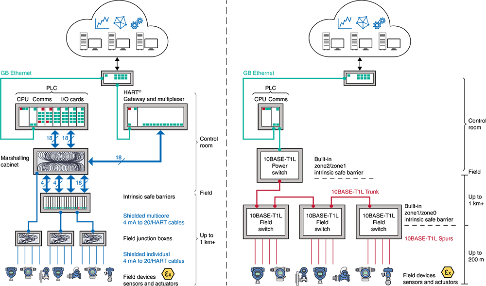
In reality, all of the above options are needed, Figure 4 shows an implementation example starting at the top with the systems installed in the control room. Normally there is no need for isolation but common mode chokes and potentially differential mode inductors are used. Since there is a connection to backbone services and sometime cloud connection multiple speed levels (up to 1 Gbps) and technologies (e.g. 10Base-T1S, 100Base-T1, 100Base-TX, 1000Base-T) are used.
The next level is the near field where the different field switches are connected. For this application a cable length of several hundred meters up to 1000 m will be used, isolation is mandatory and common mode filters as well as DMIs for power sources with high power capability is needed.
In the last section the connection from the field switch towards sensors and actuators are realized. The requirements are similar to the previous level but the DMIs used in the loads could be of smaller size as the power consumption per device is normally in the range of up to 300 mA.
Circuitry
· Additional components
To reduce the impact of possible ESD pulses there are a few components useful. Bidirectional TVS-Diodes have the advantage of a low capacity and therefore can be used in high-speed applications. Also, they are fast, which increases the response time to high-voltage events.
Capacitors are used to prevent current from flowing through one coil of the Isolated Coupled Inductor and therefore reduce unnecessary power losses. Also, an additional isolation is added to ensure the usage in safety relevant environments.
· Setup for power class 10-14
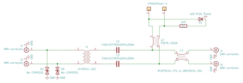
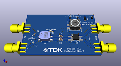
The current defined for power classes 10 to 14 will be up to approx. 600 mA and for these scenarios a so called PHY-Side injection will be applied which means that the current injection and therefore the DMI will be placed between the PHY and the CMC, therefore the CMC has to withstand the current.
Circuit
BOM
| No | Product Type | Value | TDK Part Number |
|---|---|---|---|
| C1, C2 | Capacitor | 100nF, 100V | CGA4J2X7R2A104K125AA |
| D2, D3 | TVS Diode | 5VDC, 15kV. 0.65pF | B74121U0033M060 |
| I1 | Isolated Coupled Inductor | 2.2mH, 500mA, 2kV | ICI70CGI-222 |
| L1 | Common Mode Choke |
470μH, 700mA 250μH, 100mA |
RCM70CGI-471 ADF45CGI-251 |
| L2 | Inductor | 250μH, 220mA | PID75-251M |
· Setup for power class 15
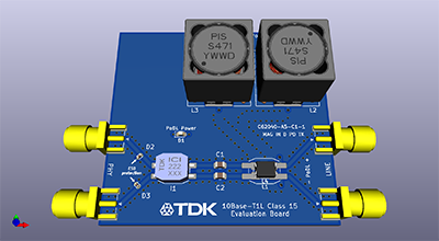
The current defined for power class 15 is much higher than in any other class with approx. 1500 mA. For this scenario, if a line-side injection will be used which means that the power injection and therefore the DMI will be placed between the CMC and the connector. In this case the CMC can be designed much smaller as it does not have to work with the power being transmitted only with the signals.
Circuit
BOM
| No | Product Type | Value | TDK Part Number |
|---|---|---|---|
| C1, C2 | Capacitor | 100nF, 100V | CGA4J2X7R2A104K125AA |
| D2, D3 | TVS Diode | 5VDC, 15kV. 0.65pF | B74121U0033M060 |
| I1 | Isolated Coupled Inductor | 2.2mH, 500mA, 2kV | ICI70CGI-222 |
| L1 | Common Mode Choke |
470μH, 700mA 250μH, 100mA |
RCM70CGI-471 ADF45CGI-251 |
| L2, L3 | Inductor | 470μH, 1800mA | PIS150H-471 |
Product Lineup
Table 3 shows the product lineup of TDK. It consists, as shown in the circuit diagram in Figure 3, of an Isolated Coupled Inductor, as well as a Common Mode Choke and a Power Inductor. The Power Inductors each refer to a power class as specified in table 2. Also, the APL power classes are shown in table 3.
| Product Type | TDK Part Number | LR / LPoDL /μH |
IEEE Power Class | APL Power Class | Idc1(typ.) /mA |
DCR (typ.) /mΩ |
Rated Current (typ.) /mA |
L x W x H /mm |
|---|---|---|---|---|---|---|---|---|
| Isolated Coupled Inductor |
ICI70CGI-102N | 1000 | 140 | 700 | 7.1 x 6.0 x 4.8 | |||
| ICI70CGI-222N | 2200 | 400 | 500 | 7.1 x 6.0 x 4.8 | ||||
| Common Mode Choke |
RCM70CGI-471N | 470 | 170 | 700 | 7.1 x 6.0 x 4.8 | |||
| ADF45CGI-251N | 250 | 3400 | 140 | 5.2 x 3.5 x 3.0 | ||||
| Differential Mode Inductors |
PID75-251M | 2x250 / 1000 | 10 | A, C | 360 | 2250 | 320 | 7.5 x 7.5 x 4.8 |
| PID100-251M | 2x250 / 1000 | 11, 13 | 645 | 1130 | 460 | 10.4 x 10.4 x 6.3 | ||
| PID120L-251M | 2x250 / 1000 | 11, 13 | 910 | 650 | 650 | 12.5 x 12.5 x 8.5 | ||
| PID120H-251M | 2x250 / 1000 | 13, 14 | 1160 | 410 | 820 | 12.5 x 12.5 x 10.5 | ||
| PID150H-251M | 2x250 / 1000 | 12, 14 | 1200 | 265 | 1200 | 15.5 x 15.5 x 14.5 | ||
| PIS150H-471 | 470 / 940 when used 2x |
15 | 3, 4 | 2000 | 245 | 2000 | 15.5 x 15.5 x 14.5 |
Contact Information
Related Links
Product Portal
-

- Multilayer Ceramic Chip Capacitors Product Information
- A comprehensive guide to information on Multilayer Ceramic Chip Capacitors from the TDK Group.
-

- SMD / SMT Inductors (Coils) Product Information
- A comprehensive guide to information on SMD / SMT Inductors (Coils) from the TDK Group.
-

- Common Mode Filters / Chokes Product Information
- A comprehensive guide to information on Common Mode Filters / Chokes from the TDK Group.
-

- TVS Diodes Product Information
- A comprehensive guide to information on TVS Diodes from the TDK Group.


