Product Overview Ferrite Shield-Type Automotive Power Inductors
The products in the SLF-H/LTF-D/CLF-NI-D series consist of wire-wound automotive grade power inductors provided with magnetic shielding by a ferrite ring core. Their lineup includes inductors with a wide variety of sizes and inductance values, which have the high reliability required to withstand the harsh environments of automotive use. They are ideal for application in various types of automotive equipment including meters, headlights, and ECMs.Contents
Product summary
TDK's lineup includes 3 types of ferrite shield-type automotive grade inductors. A summary of each series is shown in Figure 1.
| Series |
SLF-H Series |
LTF-D Series |
CLF-NI-D Series |
|---|---|---|---|
| Product Summary | Ferrite shield-type
Inductors with wires wound around a Ni-Zn core and provided with magnetic shielding by a ring core. |
Ferrite shield-type
Inductors with wires wound around a Ni-Zn core and provided with magnetic shielding by a ring core. |
Ferrite shield-type
Inductors with wires wound around a Ni-Zn core and provided with magnetic shielding by a ring core. |
| Features |
|
|
|
| Uses | For automotive equipment: ECMs, airbags, headlights, electric power steering, meters, ABS, etc. |
For automotive equipment: Sensor-related power-saving ECU applications |
For automotive equipment: ECMs, airbags, headlights, electric power steering, meters, ABS, etc. |
Product structure
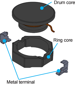
The structure of each series is shown in Figure 2. All series use a structure in which wires are wound around a drum core, and a ring core is located outside of it to provide shielding.
| Series | SLF-H Series | LTF-D Series | CLF-NI-D Series |
|---|---|---|---|
| Product Structure |
Product features
The features of each series are shown in Figure 3.
| Series | SLF-H Series | LTF-D Series | CLF-NI-D Series |
|---|---|---|---|
| Appearance | |||
| Working Temperature Range | -40~125°C (including self-heating) |
-40~150°C (including self-heating) |
-55~150°C (including self-heating) |
| Magnetic Material | Ferrite (Ni-Zn) | ||
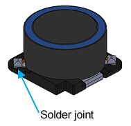
| Terminal Electrode Specifications | Metal terminal (solder joints) |
Metal terminal (weld joints) |
|
●In ferrite shield-type inductors, the magnetic flux passes through a ring core, which lowers the magnetic resistance. Compared to resin shield-types which do not have a ring core, this allows them to obtain an equivalent level of inductance with fewer windings, and can thereby reduce the RDC. Their leakage flux is also smaller, making them effective at reducing EMI as well.
Number of windings is small due to low magnetic resistance
・Reduction in RDC
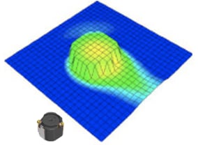
Low leakage flux due to shielded structure
・Effective at reducing EMI
Vertical near magnetic field
measurement results
(CLF-NI-D)
Development Trends
The development trends of ferrite shield-type automotive power inductors are shown in Figure 6. In order to meet the high market quality required of automotive components, these products have evolved through the application of the material technology and production methods accumulated by TDK up to this point, with properties such as support for high temperatures, fully-automated production, and welded wire connections.
List of products
A list of products by series and shape is shown in Figure 7. Detailed information can be viewed and samples can be purchased by clicking on the product type name.
| Size | SLF-H Series | LTF-D Series | CLF-NI-D Series |
|---|---|---|---|
| 3mm sqr. | 3.0x3.0mm LTF3020-D |
||
| 4mm sqr. | 4.0x4.0mm LTF4022-D |
||
| 5mm sqr. | 5.0x5.2mm LTF5022-D |
5.3x5.0mm CLF5030NI-D |
|
| 6mm sqr. | 6.3x6.0mm CLF6045NI-D |
||
| 7mm sqr. | 7.0x7.0mm SLF7045-H |
7.4x7.0mm CLF7045NI-D |
|
| 10mm sqr. | 10.1x10.1mm SLF10145-H |
10.1x10.0mm CLF10060NI-D |
|
| 12mm sqr. | 12.5x12.5mm SLF12565-H SLF12575-H |
12.8x12.5mm CLF12577NI-D |
What are power inductors?
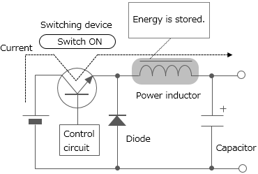
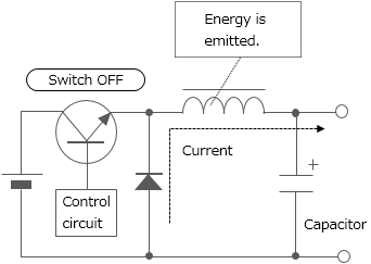
Power inductors are inductors used for power supply circuit such as DC-DC converters. They are also called power coils or power chalks. One of the inductors' characteristics is that they store energy by self-induction function. Chopper type DC-DC converters use inductors having such characteristics with switching devices for voltage conversion (see Figure 8).
Depending on the processing method, inductors can be classified into multilayer type, thin-film type, and wire-wound type. Since wire-wound type permits large current to flow, most of the power inductors are wire-wound type. Various wound-type power inductor products with ferrite or soft magnetic metal core are offered. Recently, the multilayer type and thin-film type, with which reduction of size and thickness can be achieved, are being improved to allow for larger current.
The voltage is dropped to a desired level in accordance with the duty ratio (the ratio that indicates how long the switch is ON during the switching cycle) setting.
Switching
repeated
Contact Information
Related Links
Inductor (coil) product information
Various kinds of information on TDK Group's inductors (coils) are comprehensively provided on this page.
- Lineup
- Inductors for high frequency applications Selection Guide
- Inductors for Power Circuits Selection Guide (Commercial Grade)
- Inductors for Power Circuits Selection Guide (Automotive Grade)
- Inductors for standard circuits/decoupling circuits Selection Guide
- Application Note “Selection Guide for Power Inductors in Consideration of Leakage Flux”
- Solution Guide “Solutions for silencing DC-DC converters - Measures Against Acoustic Noise in Power Inductors”


