- Power Supplies, Sources and Loads >
- DC-DC Converters
A.
*Applicable product
Power module type and on-board type power supplies
1. Measurement method prescribed by TDK-Lambda
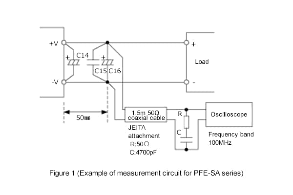
We measure output ripple and noise based on JEITA RC-9131 for AC input power supply and JEITA RC-9141 for DC input power supply.
Put the attachment (50Ω resistance and 4700pF ceramic capacitor) to the 1.5m length 50Ω coaxial cable, and solder the coaxial cable to both ends of the output ceramic capacitor (C15). Also, set the frequency band of the oscilloscope to 100MHz for usage. The method used to measure the output ripple and noise differs depending on the power supply series. For further details, please refer to the instruction manual for each series.
2. When using a 10:1 probe without using a coaxial cable
If you use a 10:1 probe that is used for normal waveform measurement without using a coaxial cable or attachment, the probe loop becomes long and susceptible to the impact of common mode noise. As a result, a great amount of output ripple and noise will be observed.
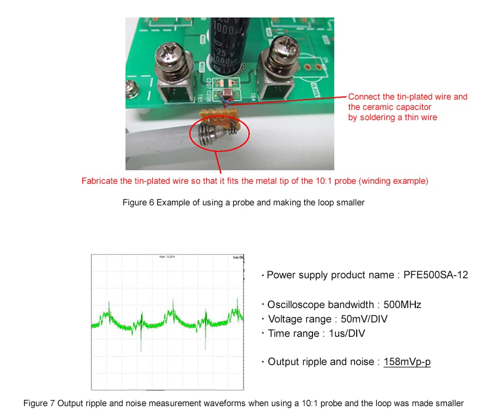
3. Measurement method which uses a 10:1 probe and reduces output and ripple noise
If you have to use a 10:1 probe, you can reduce the output and ripple noise by removing the clip and the GND wire, and then measuring with a smaller loop. However, the output and ripple noise will be larger than the measurement method specified by TDK Lambda. Therefore, please be careful when attempting to measure the correct value.
Related Information


