Product Overview Isolators/Circulators CU Series
The products in TDK's CU series of isolators/circulators are used as RF components in signal transmitting and receiving systems at locations such as mobile telephone base stations and microwave relay stations. With a diverse variety of frequencies, bandwidths, shape dimensions, terminal structures, and special specifications, their wide lineup extends from products accommodating low power for the initial stages of high-frequency amplifiers, to products accommodating high power for their final stages.This article clearly describes and explains information valuable for our customers related to the features of TDK's CU series of isolators/circulators.
Contents
- Product information 1: What are isolators and circulators?
- Product information 2: Differences between isolators and circulators
- Product information 3: Applications of isolators and circulators
- Product information 4: Main properties of isolators and circulators
- TDK's lineup of isolators and circulators
- Contact
- Related Links
Product information 1: What are isolators and circulators?
| Isolators | Circulators |
|---|---|
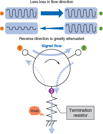
| An isolator is a product which a termination resistor is connected to any one of the terminals of the three terminals of a circulator, as shown in Figure 1. In this Figure, the termination resistor is connected to terminal ③. High-frequency signal that has entered from the terminal ① is transmitted to the terminal ② with minimal loss, as in the case of circulator. But the high-frequency signal that has entered from the terminal ② is absorbed by the termination resistor connected to the terminal ③, and is almost not transmitted to ①. Ideally, the reflection from the termination resistor is "0", but normally there is some mismatch and the power due to the mismatch is input to the terminal ③, and is transmitted to terminal ① similarly as in the circulator. As in the Figure 1, the power absorbed by the termination resistor is converted into heat and is eventually discharged to the outside (air). Usually, since the isolator is a two-terminal component, so when you look from outside it appears that the power that has entered the terminal ② is consumed in the isolator and only a small part of it is transmitted to the terminal ①. |
As shown in the Figure 2, the high-frequency signal that has entered from the terminal ① is transmitted only to the terminal ②, and the high-frequency signal that has entered the terminal ② is transmitted only to the terminal ③. And the high-frequency signal that has entered the terminal ③ will be transmitted to the terminal ①. In this way, transmission takes place only in a fixed direction, and does not happen in the opposite direction. |
Product information 2: Differences between isolators and circulators
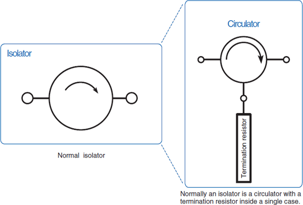
As shown in Figure 3, an isolator is a circulator which has a termination resistor connected to it.
The expression of having a circulator perform with the operation of an isolator is generally used often, so there may be cases where isolators and circulators could be confused with each other.
Product information 3: Applications of isolators and circulators
| Isolators | Circulators |
|---|---|
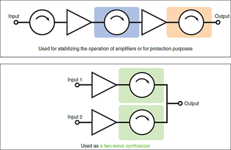
| Impedance matching of amplifiers and protection of the transistor used in the final stage, intermodulation prevention of synthesizer etc., it is used to remove the adverse effects caused by the reflected wave, as shown in Figure 4. As a result, as compared with the case of not using the isolator, the unnecessary radiation generated by the device is reduced, the circuit's operation becomes more stable ,and it could also contribute to low power consumption. |
As shown in Figure 5-(a), it is used in the antenna duplexer, and in combination with steep BPF it is used in branching circuits (Figure 5-(b)). Further, if the termination resistor built into the isolator does not meet the required standards for the reflected power, instead of using built-in termination resistor, the resistor is connected external to the circulator to use it as an isolator as shown in Figure 5-(c). By using the attenuator (ATT) instead of the termination resistor, it becomes a circulator with reflected power detection functionality (Figure 5-(d)).
|
Product information 4: Main properties of isolators and circulators
As shown in Figure 6, the main properties of isolators and circulators are "insertion loss (forward loss)", "isolation (backward loss)", and "V.S.W.R.".
Isolators and circulators possess their own frequency characteristics, so when put into actual use it will be necessary to designate their specific frequency ranges.
Circulators are evaluated by connecting a termination resistor to one of their ports and having them operate as isolators. Since circulators are circuits with three-fold symmetry, their properties are basically the same no matter which port an evaluation is made from. However, strictly speaking there are minute differences between ports, so in certain cases it may be necessary to check their properties at all three ports.
TDK's lineup of isolators and circulators
| Category | Isolators | Circulators | |||
|---|---|---|---|---|---|
| Series name | CU4S0506 | CU4S0508 | CU4S0509 | CU4S0506 | CU4S0508 |
| Appearance | |||||
| Size (mm) | 5mm sq. | ||||
| Max. height (mm) | 2.2 | 2.7 | 3.6 | 2.2 | 2.7 |
| Max. input power (W) | 5 | 5 | 5 | 5 | 5 |
| Frequency range (MHz) | 703 to 2690 | 3300 to 3700 | 3600 to 4000 | 869 to 2690 | 3300 to 3800 |
| Insertion loss (dB) | 0.7 to 1.3 | 1.0 | 1.1 | 0.8 to 1.05 | 1.2 to 1.3 |
| Isolation (dB) | 9 to 15 | 10 | 9 | 11 to 14 | 9 to 10 |
| Mounting method | SMD | ||||
| Operating temperature range | -40 to 105℃ | ||||


