Tech Notes
Solution Guide Total Solutions for NFC Circuits
- Wireless Power Transfer / NFC Antennas Sheets
- NFC Antenna Combo Rx Coil Units
- Inductors for NFC LC Filters
- NFC Single-End Circuit Baluns

Devices equipped with NFC can perform data transmission and authentication simply by being brought close to each other. This feature is rapidly being integrated into smartphones in recent times.
Additionally, its implementation is expanding to peripheral devices like wearable devices such as smartwatches.
NFC is widely used in cashless payment transactions and for connecting and authenticating peripheral devices. It holds the potential for diverse applications in realizing a touchless society.
This article introduces the main components used in NFC circuits, including NFC antennas, magnetic sheets, inductors for LC filters, and baluns for single-ended circuits.
Contents
Main Components Used in NFC Circuits

A circuit used in an NFC circuit is shown in Figure 1(a).
NFC communication operates by using an electromagnetic induction method, and consequently, loop antennas are generally used.
An antenna matching circuit and an LC filter made up of an inductor and a capacitor are inserted between the antenna and the NFC controller IC.
As shown in Figure 1(b), however, in some instances, a single-end antenna is connected. With this format, the single-end signal is converted to differential mode, and as a result, it is necessary to use a balun to perform the mode conversion.

About NFC Antennas and Magnetic Sheets
NFC communication adopts an electromagnetic induction method, and when the antenna receives a carrier wave from a reader/writer, an IC chip performs signal processing (Figure 2a).
When this antenna is installed in an electronic device such as a smart phone, there may be metal present close to the antenna.
In this case, an induced current flows in the metal and a magnetic field is produced the opposite the magnetic field generated by the reader/writer. This cancels the magnetic field from the carrier wave, shortening the communication distance and making communication impossible (Figure 2b).
As shown in figure 2c, if magnetic material is present between the coil and the metal, the high permeability has the effect of confining the magnetic flux generated from the reader/writer. As a result, the generation of the induced current in the metal can be curtailed, and good communication conditions can be maintained.
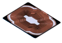
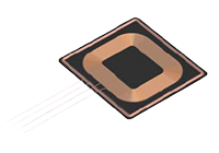
TDK provides magnetic sheets for installation between the antenna and metal and antenna units that integrate the magnetic sheet and antenna.
| NFC Antenna (Thin Type) |
Integrated NFC antenna | NFC Antenna (WPC Rx Integrated Type) |
Magnetic sheet for NFC | |
|---|---|---|---|---|
| Series | MSC series Under development | WCT series | WR series | IFL/IFQ/IBQ/WCF/IFW series |
| Product Exterior View | 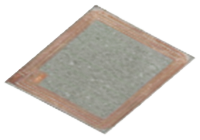
|
|
|

|
| Features | By embedding the antenna coil in a magnetic sheet, we have achieved a thickness of less than 100um | Integrated with non-contact charging coil, contributing to space saving | Components ideal for installation in mobile devices are created by integration with an electromagnetic induction type wireless power transfer coil. | High permeability and low magnetic loss at 13.56 MHz |

About Inductors for NFC LC Filters
Inductors for LC filters are required to produce narrow tolerances in order to reduce loss due to impedance mismatch with the antenna.
As shown in Table 2, TDK’s MLF/MLJ series are both product lineups with J tolerances (± 5%).
To prevent a decrease in antenna output, it is also important to control inductor loss at 13.56 MHz, the communications frequency.
To do this, it is necessary that the AC resistance (Rac) be kept low and that a low Rac be maintained even when current is applied.
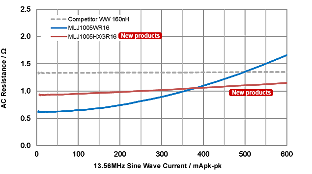
TDK’s MLJ-W series achieves low Rac, while the new MLJ-H series achieves low Rac even when a large current is applied.
As can be seen in Figure 3, the Rac of the MLJ1005H remains low even in the high current range.
On the other hand, the Rac of the MLJ1005W is low in the low current range, and the optimal product can be selected depending on the actual current values used.
| Series | MLF1608D MLF1005V |
MLJ1608W MLJ1005W |
MLJ1005HNew products |
|---|---|---|---|
| type | STD | High Current Low Loss |
Super High Current Super Low Loss |
| size [mm] | 1608 / 1005 | 1608 / 1005 | 1005 |
| L tolerance [%] | +/- 5 | +/- 5 | +/- 5 |
| L value [uH] | 0.10 – 0.82 (1608 size) 0.10 – 0.56 (1005 size) |
0.10 – 0.56 (1608 size) 0.075 – 0.56 (1005 size) |
0.056 - 0.20 |
| Current [mA] | 70 – 200 (1608 size) 120 – 180 (1005 size) |
400 – 800 (1608 size) 250 – 550 (1005 size) |
480 - 950 |

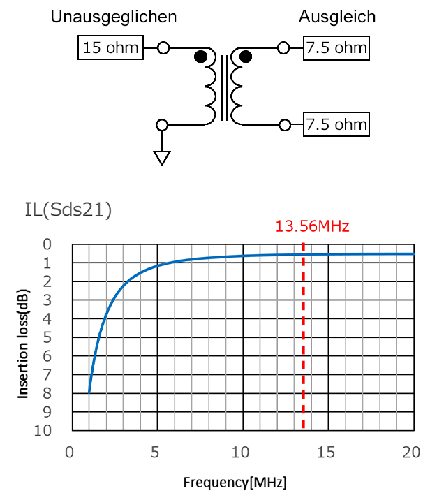
About Baluns for NFC Single-Ended Circuits
A balun is an element used to switch between a balanced circuit and unbalanced circuit. It is also possible to convert the impedance by changing the turn ratio of two coils.
Baluns used in NFC circuits often have a turn ratio of 1:1, and the keep insertion loss in the 13.56 MHz band low.
TDK’s proprietary technology makes possible slimmer and more compact products.
| Series | ATB16106HD-15011-T10 |
|---|---|
| Product Exterior View | 
|
| size [mm] | 1610 |
| height [mm] | 0.65 max |
| UB/B Imp [ohm] | 15:15 |
| Rated Current [mA] | AC 400mA RMS |
| Features | Compact, low-profit type ideal for NFC use |