TDK NTCRP Series Insulation Resistance and Dielectric Withstand Voltage Test Methods

Insulation resistance and dielectric withstand voltage are particularly crucial parameters for ensuring both safety and reliability during end-user operation.
This article aims to explain the test methods for evaluating the insulation resistance and dielectric withstand voltage of the NTCRP series.
Contents
- Overview of NTCRP Series Products
- Insulation Resistance of the NTCRP Series
What is Insulation Resistance
NTCRP Series Insulation Resistance Test Method - Dielectric Withstand Voltage of the NTCRP Series
What is Dielectric Strength
NTCRP Series Dielectric Strength Test Method
NTCRP Series Product Overview
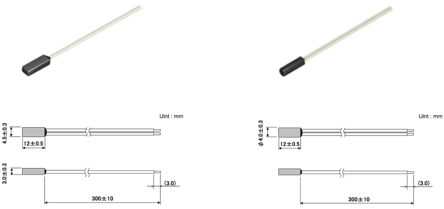
This product is a glass-encapsulated NTC thermistor sealed in a PPS case. The case is the smallest in the industry by resin injection molding. Depending on the environment/shape of the mounting location, you can choose from two types: rectangular or cylindrical. The rectangular type is suitable for a flat surface such as square wires for motors and busbars, while the cylindrical type is ideal for wrapping round copper wires into bundles. If you have any questions about the installation method, please contact us, and our experienced technical staff will propose the optimal mounting solution.
Insulation Resistance of the NTCRP Series
What is Insulation Resistance
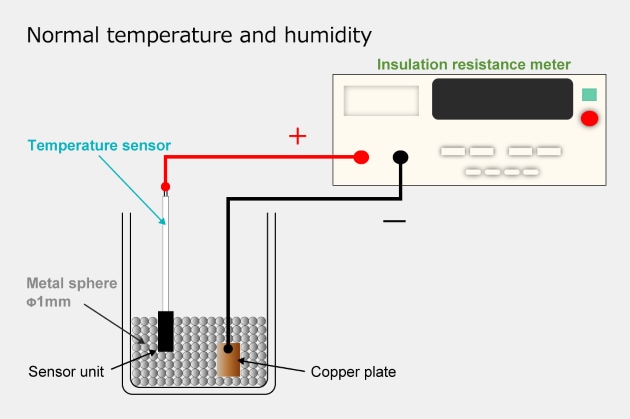
The insulation resistance of an NTC thermistor indicates the effectiveness of the thermistor’s external insulating material in preventing electrical short. For the NTCRP series, insulation resistance is verified by applying a voltage across the thermistor and the conductive materials surrounding it.
| Test Method | Place the NTCRP series sensor and a copper plate inside a metal sphere. Apply voltage across the metal sphere and both ends of the electrical wire, and measure the insulation resistance. |
|---|---|
| Target | Between the sensor part and lead wire |
| Applied Voltage | DC 500V |
| Environment | Under normal temperature and humidity conditions |
| Sensor insertion length into the metal sphere | Approx. 10 mm |
| Specifications | 100 MΩ or higher |
Dielectric Withstand Voltage of the NTCRP Series
What is Dielectric Withstand Voltage
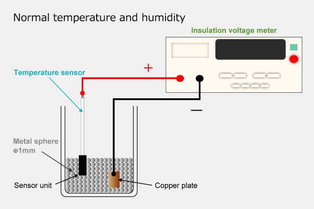
Dielectric withstand voltage for NTC thermistors assures that no dielectric breakdown will occur when an extremely high voltage is applied to the thermistor. In the case of the NTCRP series, this is ascertained by applying a high voltage to both the thermistor and the conductive material surrounding it, and confirming the absence of leakage current.
| Test Method | Place the NTCRP series sensor part and a copper plate inside a metal sphere, and confirm there are no issues by applying voltage between the metal sphere and both ends of the electrical wire. |
|---|---|
| Target | Between the sensor part and lead wire |
| Applied Voltage | AC 1500V |
| Duration | 1 minute |
| Environment | Under normal temperature and humidity conditions |
| Sensor insertion length into the metal sphere | Approx. 10 mm |
| Specifications | No current leakage; Leakage current setting: 0.5 mA |


