Q.
Capacitor guide of ESD (6): How does TDK recommend selecting the right capacitor for ESD?
- Capacitors >
- Multilayer Ceramic Chip Capacitors
A. Through experimentation, TDK has determined that there are three critical parameters that help the design engineer determine the best value for an ESD capacitor: voltage breakdown, capacitance, and DC bias.
-
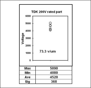
Voltage breakdown is a test method used to quantify the voltage level strength of a capacitor. DC voltage is applied across the capacitor at a fixed voltage ramp rate (i.e. 100v/s) until the part fails. This determines the maximum sustained voltage the capacitor can withstand but does not directly indicate maximum ESD voltage level.
Example of Vbd test results -
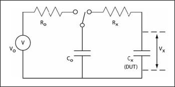
The DUT effect refers to the effective resultant voltage seen across the capacitor under test (DUT) in the ESD test circuit.
Nodal analysis shows that the relationship between the resultant voltage (VX) across the DUT (CX) as
By keeping the source voltage (VO) and charge capacitor (CO) constant, the relationship between resultant voltage (VX) and the DUT capacitor (CX) are inversely proportional. This means that as you select a higher value CX, VX decreases.
To illustrate the DUT effect, take as an example a 4kV (VO) ESD requirement for a 1000pF capacitor (CX). Also assume we are using the AEC-Q200 test method which uses CO = 150pF. The DUT effect relationship shows that with 4kV applied, CX only sees 521.7V (VX). - When DC voltage is applied to a ceramic capacitor, the effective capacitance may be different from the nominal capacitance. DC Bias is typically expressed in percent capacitance change from nominal.
DC Bias is largely due to the dielectric material. Of course other design and construction factors play a role as well. For Class I dielectrics such as C0G, the change is relatively flat. For Class II such as X7R and X5R, you may see a slight increase in capacitance initially which is immediately followed by a steady decrease as you approach the rated capacitance. Typically for Class II dielectrics, the DC bias is between -10% to -70%.
As the applied voltage increases, effective capacitance decreases. DC bias is repeatable and does not have any destructive effect on the performance or life of the capacitor as long as you do not exceed the rated voltage.
>>Multilayer Ceramic Chip Capacitors Product site
For any other product-related questions or inquiries, please contact us throughone of our sales representatives or this website.


