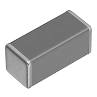
Multilayer Ceramic Chip Capacitors
CGA7G1C0G3F220K110KA
|
|
Size
| Length(L) |
|
| Width(W) |
|
| Thickness(T) |
|
| Terminal Width(B) |
|
| Recommended Land Pattern (PA) |
|
| Recommended Land Pattern (PB) |
|
| Recommended Land Pattern (PC) |
|
| Recommended Slit Pattern (SD) |
|
Electrical Characteristics
| Capacitance |
|
| Rated Voltage |
|
| Temperature Characteristic |
|
| Q (Min.) |
|
| Insulation Resistance (Min.) |
|
Other
| Operating Temp. Range |
|
| Soldering Method |
|
| AEC-Q200 |
|
| Packing |
|
| Package Quantity |
|
| FIT (Failure In Time) |
|
Tech Info
Documents
-
Specification
-
RoHS Certificate
-
SVHC / REACH Certificate
-
Selection Guide for Automotive MLCC
-
[Promotion Video] xEV Wireless Charger Resonant Circuit Applications
-
[Solution Guide] (MLCC C0G Guide for Resonance Circuit Vol.1) Features of High voltage MLCCs with C0G Characteristics and Replacement Solutions
-
[Solution Guide] (MLCC C0G Guide for Resonance Circuit Vol.2) Application to EV wireless power transfer systems
-
[Solution Guide] (MLCC C0G Guide for Resonance Circuit Vol.3) Application to EV plug-in power charging systems
-
Sample Kits
Technical Support Tools
Related articles
Characteristic Graph
Loading graph, please wait...
Customer who viewed this product also viewed

Multilayer Ceramic Chip Capacitors
C0603X7S0G224K030BC
Capacitance=0.22μF
Edc=4V
T.C.=X7S
LxWxT:0.6x0.3x0.3mm
General

Multilayer Ceramic Chip Capacitors
C2012X5R1E106K085AC
Capacitance=10μF
Edc=25V
T.C.=X5R
LxWxT:2x1.25x0.85mm
General

Multilayer Ceramic Chip Capacitors
C4520C0G3F101K200KA
Capacitance=100pF
Edc=3000V
T.C.=C0G
LxWxT:4.5x2x2mm
High Volt. (1000V and over)

Multilayer Ceramic Chip Capacitors
C4520C0G3F470K160KA
Capacitance=47pF
Edc=3000V
T.C.=C0G
LxWxT:4.5x2x1.6mm
High Volt. (1000V and over)

Multilayer Ceramic Chip Capacitors
C4520C0G3F680K200KA
Capacitance=68pF
Edc=3000V
T.C.=C0G
LxWxT:4.5x2x2mm
High Volt. (1000V and over)

Multilayer Ceramic Chip Capacitors
CGA2B2X7R1H222K050BE
Capacitance=2.2nF
Edc=50V
T.C.=X7R
LxWxT:1x0.5x0.5mm
Soft termination
AEC-Q200

Multilayer Ceramic Chip Capacitors
CGA4J2X7R1H224K125AE
Capacitance=0.22μF
Edc=50V
T.C.=X7R
LxWxT:2x1.25x1.25mm
Soft termination
AEC-Q200

Multilayer Ceramic Chip Capacitors
CGA6M1C0G3A682J200AC
Capacitance=6.8nF
Edc=1000V
T.C.=C0G
LxWxT:3.2x2.5x2mm
High Volt. (1000V and over)
AEC-Q200

Multilayer Ceramic Chip Capacitors
CGA6M1C0G3B102G200AC
Capacitance=1nF
Edc=1250V
T.C.=C0G
LxWxT:3.2x2.5x2mm
High Volt. (1000V and over)

Multilayer Ceramic Chip Capacitors
CGA6M1C0G3B102J200AC
Capacitance=1nF
Edc=1250V
T.C.=C0G
LxWxT:3.2x2.5x2mm
High Volt. (1000V and over)


 This will be displayed when you


