Product Development Utilizing TDK's Proprietary Pattern Coil Technology

Product Lineup of Pattern Coils
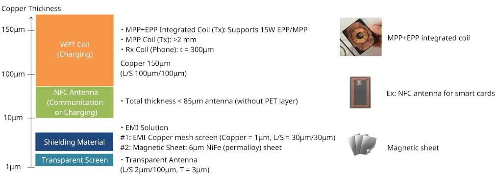
TDK's proprietary pattern coil technology allows for precise and flexible adjustments to the thickness of copper traces based upon application requirements. This capability enables highly customizable coil designs that are not achievable with conventional copper coil technologies such as those created by etching. The end-product lineup includes: coils/antennas for Wireless Power Consortium (WPC) Qi standard wireless power transfer (WPT) coils, antennas for the AirFuel standard of WPT, other non-Qi standard WPT coils, RFID/NFC antennas for both communication and power, and EMI mesh screens. Further thickness reduction can be achieved by embedding the copper antenna into the adhesive layer used to adhere the antenna to its magnetic shield, where the shield is used to contain the magnetic flux (Ø) of the magnetic field (H). These capabilities facilitate the use of patterns coils in a wide variety of end applications. Typical copper thickness versus end application information is shown in Figure1.
TDK MP-A28 Ultra-Thin WPT Pattern Coil
With the increasing prevalence of wireless power or charging for mobile devices, such as smartphones, the demand for convenient charging in various settings, including inside automobiles, has been growing. The Qi-approved MP-A28 coil, through its unique patterning process, reduces copper thickness to 150μm per side, achieving a remarkable overall thickness of just 0.76mm. This is one-fifth the thickness of conventional wire wound coils, which are around 3.8mm. Also, a unique single coil pattern has been implemented which reduces part count and board space. With these features, the product weight has been reduced by 76%, sitting now at 12.5g. These comparisons are shown in Figure 2. The thin and lightweight design of electronic components for automotive use is a critical theme, and TDK’s mass-produced MP-A28 coil offers advantages in thinness, reduced weight, and part reduction, enabling the integration of wireless charging technology into space-limited layouts.
TDK Ultra-Thin NFC Antenna MSC Series
NFC communication, used for contactless payments, secured access, and personal authentication, requires a magnetic resonance loop antenna. However, communication can be hindered by nearby metal environments, so a combination of an antenna plus a magnetic shield may be necessary.
As NFC-equipped devices become smaller and lighter, the integrated loop antennas also need to be smaller and/or thinner, which can create challenges for traditional antenna technologies. This is highlighted in Figure 3.
TDK's pattern coil NFC antennas make use of TDK’s magnetic shield manufacturing technology to embed the antenna into the adhesive layer attached to the magnetic shield, thus achieving further antenna thickness reduction. Additionally, optimizing the design with the best magnetic material maximizes performance and enables even thinner magnetic sheets.
The NFC Forum has also released a standard where NFC antennas and frequencies are used to wirelessly charge low power devices like wearables. The pattern coil’s antenna configuration flexibility is advantageous when small antenna sizes and/or irregular shapes are required due to the physical dimensions of the low power to-be-charged device.
NFC Antenna for Metal Credit Cards
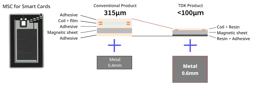
Contactless payments using NFC are becoming more widespread, even for credit card transactions, with nearly all newly issued cards now equipped with NFC communication capabilities. Premium credit cards now have an option to be made with some content of metal to create a sense of luxury and exclusivity. However, integrating NFC wireless communication into these cards may require thinning the metal to accommodate the antenna, potentially compromising multiple aspects of the premium card's design … including weight. A comparison between a current metal credit card and the advantageous pattern coil antenna plus shield is shown in Figure 4.
The MSC Series complies with contactless communication standards for credit cards while achieving extreme thinness, allowing metal cards to maintain their luxurious feel while supporting industry communication standards.
NFC Antenna for Transparent Cards
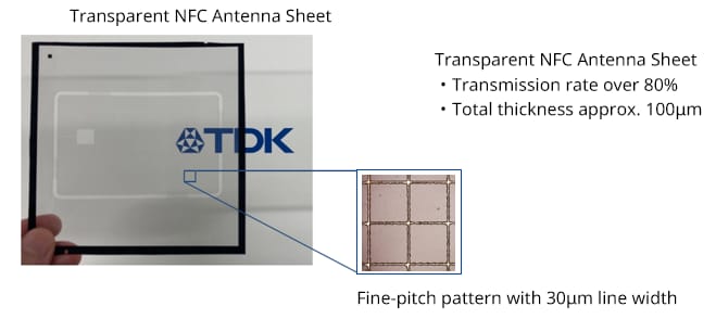
One of the biggest current trends in credit cards is differentiation from other banks and respective cards, and one of the more compelling approaches is a transparent card. Although some of the materials used in transparent cards are entirely transparent, the NFC antenna for wireless communication cannot be made 100% optically transparent, thus preventing the realization of a fully transparent card with wireless communication functionality. However, TDK's pattern coil antenna technology has enabled the development of a fine line pattern utilizing the same electro-plating technology with over 80% transparency. Using this NFC antenna makes it possible to create a uniform appearing transparent card and is shown in Figure 5.
Ultra-Thin Permalloy Sheet IPM Series
Electromagnetic interference [EMI] noise suppression within electronic devices is essential for ensuring proper operation and compliance with regulatory standards. However, It can be difficult to completely suppress unwanted noise in circuit design, and shielding materials are often used as a countermeasure against both conducted and radiated noise.
Inexpensive metal cases are often used as shielding materials, but while they are effective for high-frequency noise, they are less effective for low-frequency noise, and the thickness of the case must be increased to achieve the necessary shielding performance.
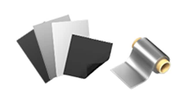
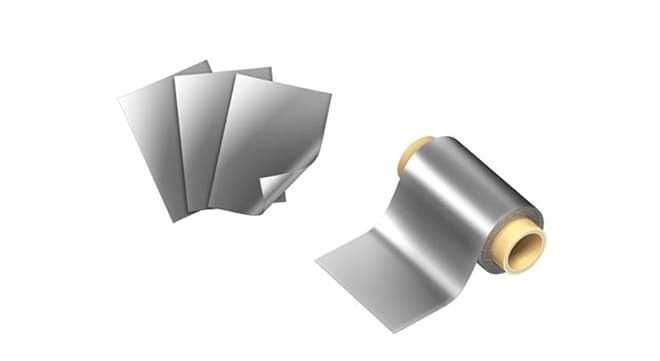
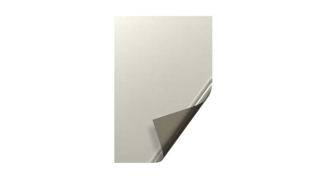
The IPM series is an ultra-thin soft magnetic metal sheet, and the use of Permalloy, a high magnetic permeability material, dramatically increases its effectiveness against low-frequency noise, and below 500 kHz, it shows shielding performance equivalent or superior to that of a stainless steel plate which is 100 times thicker.
A single magnetic layer version of the IPM01 series is shown in Figure 6.
IPM Series Applications
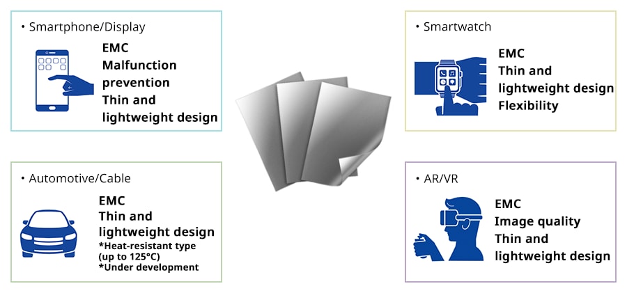
With the continued miniaturization, thinning, and multi-functionality of electronic devices, EMI noise suppression in smartphones and other electronics has become increasingly important. TDK’s IPM01 series offers leading-edge high permeability magnetic materials, with an integrated copper layer therefore optimizing EMI noise suppression in various electronic devices and in applications featured in Figure 7. TDK’s IPM01 material is available on rolls, in sheet format, and in custom sizes and shapes. A heat-resistant design, capable of operating in environments up to 125°C, is currently in development and is scheduled for mass production in 2025.

