Challenges in Next Generation Power Semiconductors and Application of MLCCs
<br>
This application note introduces the utility of Multilayer Ceramic Capacitors (MLCCs) in high-voltage snubber circuits, key considerations for their selection, and TDK's evaluation examples under high dV/dt conditions. We hope this serves as a valuable reference for those considering MLCCs for snubber circuit designs.

 Contact Us
 Challenges in Next-Generation Power Semiconductors
While next-generation power semiconductors will enable high-speed switching, the following three challenges can be identified.
Challenge 1: Noise
The noise generated contains high-frequency components, making it easy to propagate and requiring EMI countermeasures.
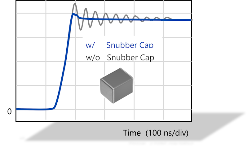
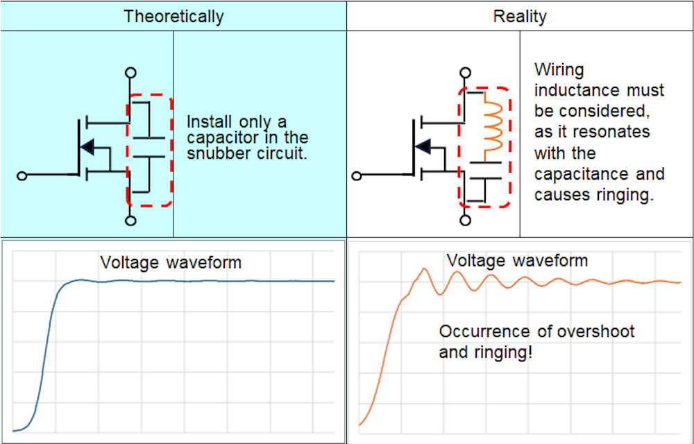
The main factors are ringing and overvoltage.
In particular, ringing occurs due to the resonance between the parasitic inductance of wiring in the switchon group and the parasitic capacitance of the semiconductor device.
Issue 2: Overvoltage
Overvoltage tends to occur with sudden voltage build-ups, that is, high dV/dt levels. Therefore, measures are required from the perspective of device protection.
Issue 3: Heat generation due to high currents
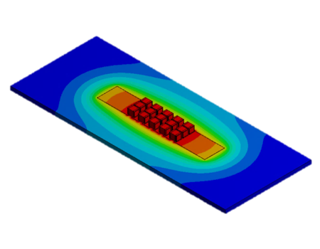
High dV/dt and di/dt generate large currents, and the equivalent series resistance (ESR) of MLCCs generates heat.
Therefore, MLCCs must be used to ensure temperature rise within an appropriate range (ΔT ≦20°C).
Utility of MLCCs in Snubber Circuits for Next-Generation Power Semiconductors
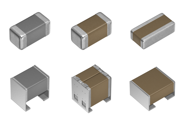
With next-generation power semiconductors such as SiC and GaN, the challenge lies in achieving both miniaturization and surge voltage suppression. This is due to the trend toward thinner power modules. Because MLCCs are non-polar, compact, low-profile, and feature low ESL and low ESR, as well as suitability for high-temperature environments, they are a strong choice for snubber circuits.
MLCC Feature (1): Non-polarity
Since snubber circuits exhibit voltage polarity reversal, non-polarized film capacitors or MLCCs are used.
MLCC Feature (2): SMD, compact, low-profile
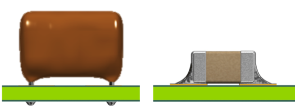
MLCCs support SMD and, due to their compact size and low profile, contribute to the miniaturization of the set.
MLCC Feature (3): Low ESL and Low ESR
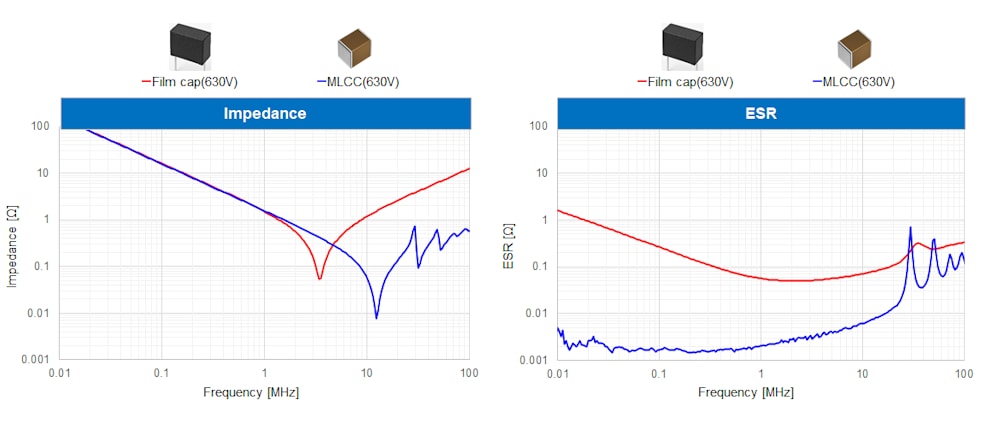
Low ESL and low ESR are important for suppressing the overall inductance of the circuit and for efficient noise removal.
MLCC Feature (4): Adaptation to high-temperature environments such as 125°C
MLCCs are made of ceramics, making them suitable for use in relatively high-temperature environments.
Selection Criteria for Snubber Capacitors in Next-Generation Power Semiconductors
In snubber circuits for next-generation power semiconductors, it is important to select based on the characteristics of MLCCs to properly suppress overvoltage and reduce noise.
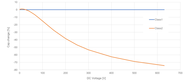
Figure 5: DC bias characteristics
・MLCC Selection Point 1:Selecting MLCCs: Class 1 or Class 2?
Although Class 1 MLCCs have a smaller initial capacitance than Class 2, they offer excellent stability in electrical characteristics. Class 1 features excellent DC bias characteristics, no capacitance changes due to voltage application, and extremely low temperature dependence of capacitance. Furthermore, Class 1 has a much lower ESR compared to Class 2, resulting in less loss and reduced self-heating. On the other hand, Class 2 is compact and has a high initial capacitance, but its capacitance decreases due to DC bias. Although Class 2's ESR is relatively low, it is larger than Class 1 MLCCs, so self-heating tends to be steep, so caution is needed.
・MLCC Selection Point 2: Effective capacitance at actual operating voltage is important
Class 2 has DC bias characteristics, so the effective capacitance during operation is important. If capacitance is insufficient, operation may become unstable or noise removal may be insufficient, so please select items that consider effective capacitance at the actual operating voltage.
・MLCC Selection Point 3: Selecting MLCCs: Self-heating ΔT should be 20°C or below
Capacitors block DC and allow alternating current to pass through. High-frequency noise currents pass through the MLCC and are directed to GND. When current passes through the capacitor, heat loss occurs at W = ESR × I^2 according to the Joule heat formula. This is self-heating. Since the self-heating of capacitors affects the lifespan of MLCCs, please design with consideration for substrate heat dissipation, ensuring self-heating is within 20°C and within the guaranteed temperature.
・MLCC Selection Point 4: Consideration for operating temperature and environment
For snubber applications, it is common to choose products with a maximum guaranteed temperature of 125°C or 150°C. This is because the effect of element agitation heat must be considered when placed near switching elements or heat-generating components. Since the snubber circuit is subjected to current, the MLCC generates self-heating, so please design it to keep the temperature within the guaranteed range, including these thermal factors.
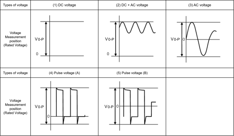
・MLCC Selection Point 5: Selection of Rated Voltage
The maximum value of the voltage waveform (Vp-p or the peak value of DC + surge voltage) must be selected so that it remains within the rated voltage. Please design the circuit so that the MLCC operates within its rated voltage, including surge voltage. Please note that the withstand voltage is the tolerance against a single abnormal voltage such as a lightning surge; if such voltage is applied repeatedly, the circuit must be designed to stay within the rated voltage. For Class 1 MLCCs of C1005 size or larger, we provide graphs of maximum allowable current / maximum allowable voltage for each part number, so please make use of them.
TDK's Component Evaluation Examples in High dV/dt Environments
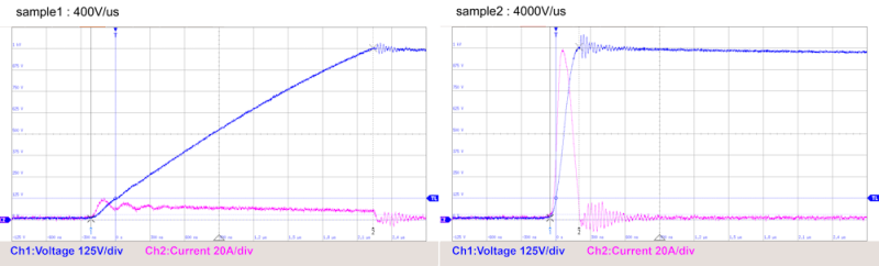
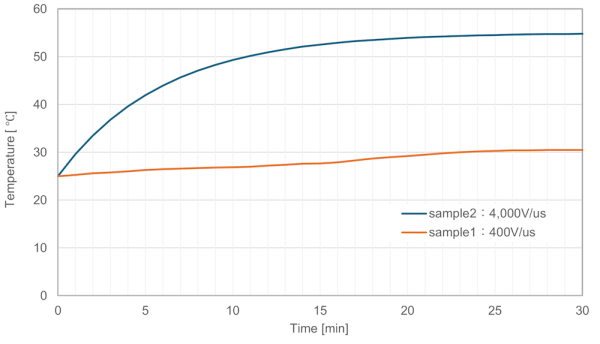
We frequently receive inquiries regarding the potential impact on MLCCs in applications where large currents with high dV/dt and high di/dt are applied.To address these needs, TDK has established a test environment capable of applying high dV/dt and high di/dt directly to MLCCs.As an evaluation example within our established test environment, we prepared samples subjected to two different dV/dt conditions—400V/μs and 4000V/μs—for a fixed duration, and then applied AC voltage to them. Upon observing the self-heating, it was confirmed that the samples subjected to the higher dV/dt exhibited a greater temperature rise.While trends vary depending on the product and application conditions, any increase in MLCC self-heating impacts product lifespan. Therefore, it is crucial to evaluate MLCCs by applying voltage waveforms that closely simulate actual operating conditions.
Summary & Contact: TDK's Support for Snubber Circuits in Next-Generation Power Semiconductors
With the increasing adoption of next-generation power semiconductors, overvoltage issues caused by high dV/dt have become more critical. As the adoption of MLCCs for overvoltage and EMI mitigation continues to grow, this article has outlined the key considerations for using MLCCs in snubber circuits and shared TDK’s evaluation examples involving high dV/dt.
TDK offers a comprehensive range of noise countermeasure components for power semiconductors, as well as technical support for evaluating the effects of high dV/dt on MLCCs. Whether you need component proposals, evaluation, or verification for your snubber capacitor selection, TDK provides total support. Please feel free to contact us to enhance reliability and noise suppression in your power semiconductor circuit designs.
 MLCC High Voltage Snubber Applications

Related Links