How to Use the Thermal Model for Simcenter Flotherm
In onboard chargers for electric vehicles and in wireless power transfer systems, power levels are increasing while board enlargement is not acceptable, requiring increasingly compact designs. Moreover, MLCCs used in the resonant circuits of these systems are subjected to very high AC voltages, making MLCC self‑heating a more significant issue than before.
Against this backdrop, the importance of thermal design in product development has grown, and detailed thermal simulations that model mounted components are required.
To meet these needs, TDK offers MLCC thermal simulation models. Using this tool enables pre‑evaluation of heating risks and optimal component selection.<br>
This article provides an overview of TDK’s thermal simulation models and instructions on how to use them.
 Contact Us
 Model overview
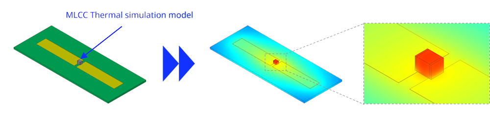
TDK provides thermal simulation models for multilayer ceramic capacitors (MLCCs) that can be used with the electronic‑device design support tool "Simcenter™ Flotherm™". By setting the assumed heat generation in the thermal simulation model, the MLCC surface temperature can be calculated. The model file format is EROM (embedded BCI‑ROM); the product’s internal structure and material properties are treated as a black box, but the model is a reduced‑order model that achieves analysis accuracy comparable to detailed models.
※ Simcenter Flotherm is a registered trademark of Siemens Industry Software Inc.
Where to obtain the model
You can download the MLCC thermal simulation model library from the TVCL page.
After agreeing to the terms of use, download the .library file.
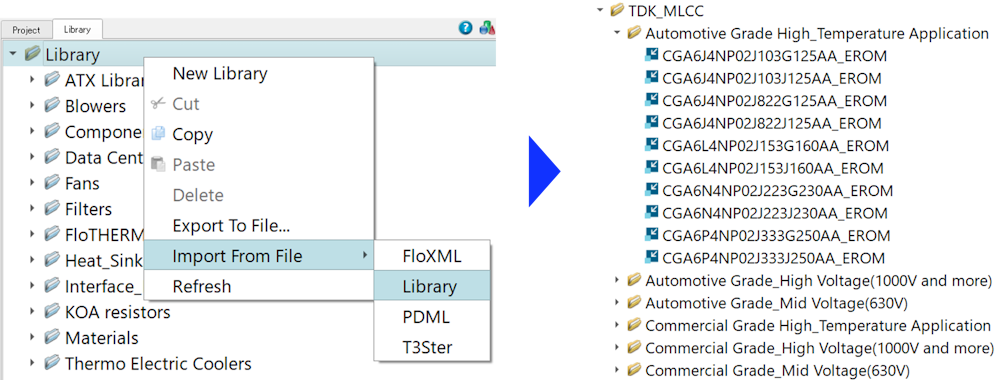
In Simcenter Flotherm, right‑click the "Library" folder, choose "Import from File", and select the downloaded .library file. The model library will be imported into the Library.
The thermal simulation models are organized into folders by product category.
Model structure
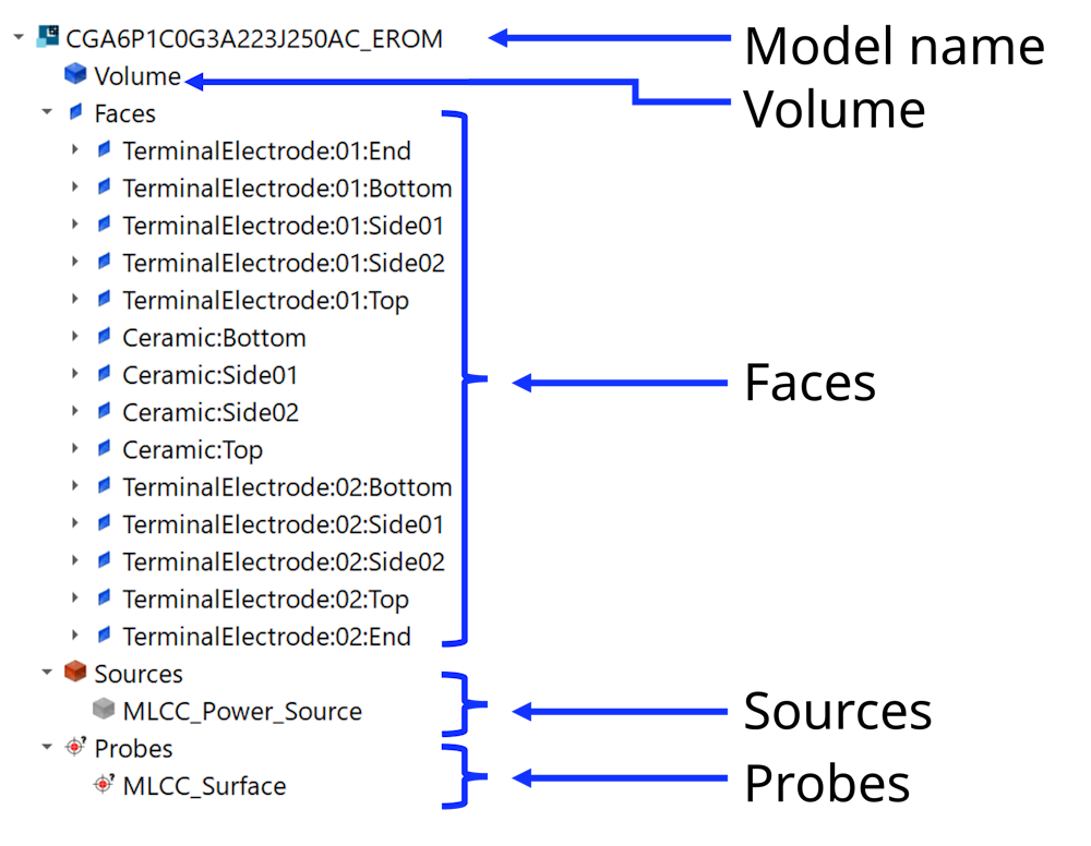
The structure of the thermal simulation model (EROM) is explained using "CGA6P1C0G3A223J250AC_EROM" as an example. The EROM is represented as hierarchical groups of nodes, as shown in Figure 3.
| Model name | The model name follows our catalog part number. For details on catalog part‑number nomenclature, refer to the product datasheet or our Product Center. |
| Volume | Represents the EROM volume of the MLCC. The internal structure is treated as a black box. |
| Faces | Calculates heat transfer from the EROM faces to the environment. Surface conditions are preconfigured, but various parameters (e.g., surface‑to‑solid thermal contact resistance, emissivity, color) can be modified. |
| Sources | Defines heat generation occurring within the MLCC. |
| Probes | Parts used for temperature monitoring. In this model, a probe is placed at the center of the MLCC surface. |
Local grid (meshing) settings are preconfigured for the EROM. These grid settings can be changed as needed.
How to use the model
Transfer the EROM into the project
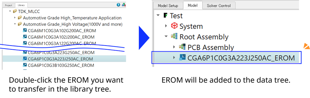
In the Data Tree, select the assembly.
In the Library Tree, select the imported library. Double‑click the EROM for the desired part number to add it to the Data Tree.
In the Data Tree, place the EROM so that it is positioned below the object it will contact.
Initial position and orientation of the EROM
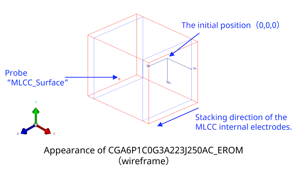
The initial position and orientation of the EROM transferred into the project are set as shown in the figure. The center of the MLCC bottom face is placed at (0, 0, 0), and the direction from this point toward the probe named "MLCC_Surface" corresponds to the stacking direction of the MLCC internal electrodes.
You may place the EROM at any desired position and orientation.
Heat generation (power) setting
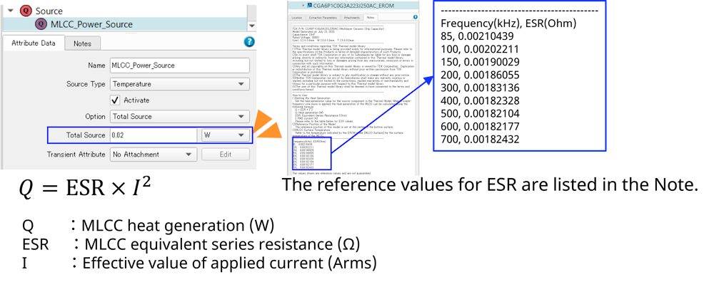
In the EROM, select "MLCC_Power_Source" under the Sources node.
Set the desired heat generation (power) value in the attribute data's "Total source" field.
The MLCC heat generation can be calculated from the ESR at the operating frequency and the RMS value of the applied current using the following equation.
Note: Refer to the Note section of each model for the ESR values of the respective product. The ESR values provided are reference values only and are not guaranteed.
Run the simulation
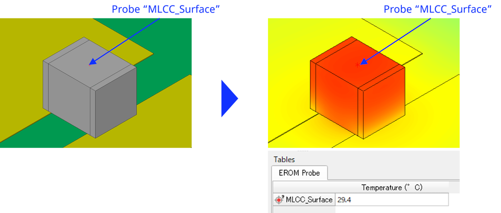
After completing the settings above, run the analysis (start the simulation).
The surface of the MLCC is set as the monitoring point, and the surface temperature results can be viewed on the table.
You can create a surface plot to inspect the surface temperature distribution.
Scope of application
This thermal simulation model assumes a single‑frequency sinusoidal voltage applied to MLCCs. If the model is used outside the frequency and voltage ranges specified in the allowable‑voltage chart, the results may be invalid. For detailed characteristics of each product, please refer to the product datasheet.
Supported Flotherm version
This thermal simulation model was created using Simcenter Flotherm 2410 and is compatible with Simcenter Flotherm 2410 and later versions. Depending on your environment, the model may not function correctly; please be aware of this in advance.
※ The simulation model version may be changed without prior notice.
Summary
In this article, we presented an overview of, and usage instructions for, the thermal simulation models for multilayer ceramic capacitors (MLCCs) that can be used with Simcenter™ Flotherm™. Although the models are simplified version, they achieve analysis accuracy comparable to detailed models. We hope these models help improve the efficiency of your product design.
In addition, TDK provides a tool that recommends MLCC series/parallel configurations based on the drive conditions of LC resonant circuits—please consider using it as well.

Related Links