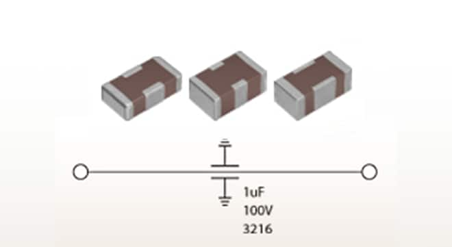
How to use the "YFF Series" 3-Terminal Feed-through filter for noise suppression and reducing the number of MLCCs

Additionally, in automotive electrical systems, there is an increasing demand for low-ESL type products to improve safety and comfort and to meet the demands of infotainment.
This Solution Guide introduces various solutions utilizing TDK's advanced low-ESL components, the "YFF Series" 3-terminal feed-through filter.
Structure of the 3-Terminal Feed-Through Filter
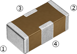
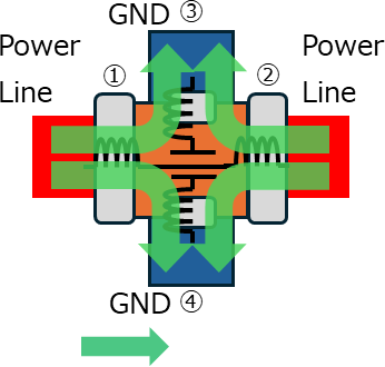
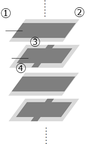
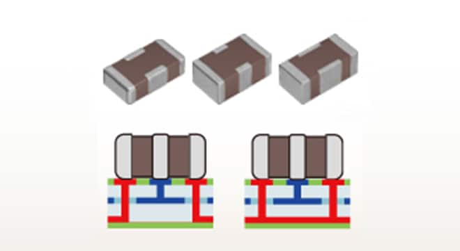
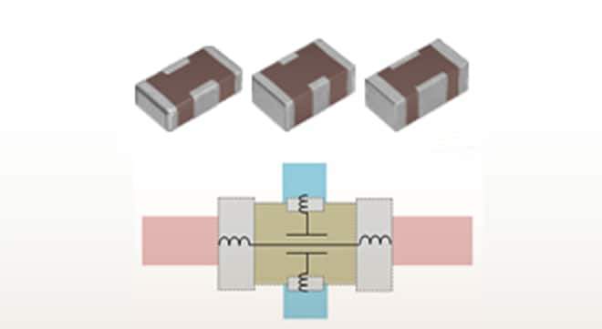
The appearance and internal structure of the 3-terminal feed-through filter are illustrated in the conceptual diagram.
Although it is generally called ""3-terminal"", it is actually composed of two terminal electrodes and two ground electrodes. It has an internal structure in which internal electrodes for conduction and internal electrodes for grounding are alternately layered.
Appearance
Terminal electrode Terminal electrode Ground electrode Ground electrodeNoise current path image
:Noise currentInternal structure (schematic diagram)
Internal electrodefor power supply Internal electrode for
grounding
The feed-through structure shortens the distance between the capacitor and the ground, resulting in lower ESL and enhanced noise suppression.
The parallel effect of two ground electrodes further reduces ESL.
Comparison of Impedance-Frequency Characteristics with Other MLCCs
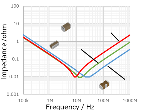
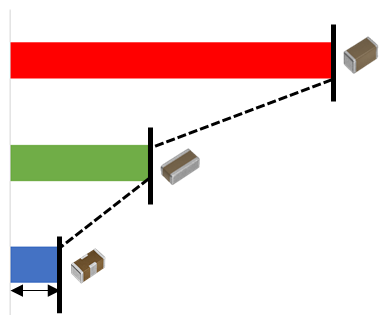
Capacitors for reducing high-frequency noise must have a low ESR (Equivalent Series Resistance) and ESL, as well as a higher SRF (Self Resonant Frequency).
ESR and ESL are influenced by the resistance and inductance of terminal electrodes and internal electrodes.
Therefore, a reverse geometry capacitor, in which a low ESL is achieved by reversing the longitudinal direction and width direction of the terminal electrodes of a normal 2-terminal multilayer ceramic chip capacitor (MLCC) to make the current route wider and shorter, is also effective as a noise countermeasure.
TDK's YFF series 3-terminal feed-through filter achieves even lower ESR and ESL compared to these reverse geometry capacitors.
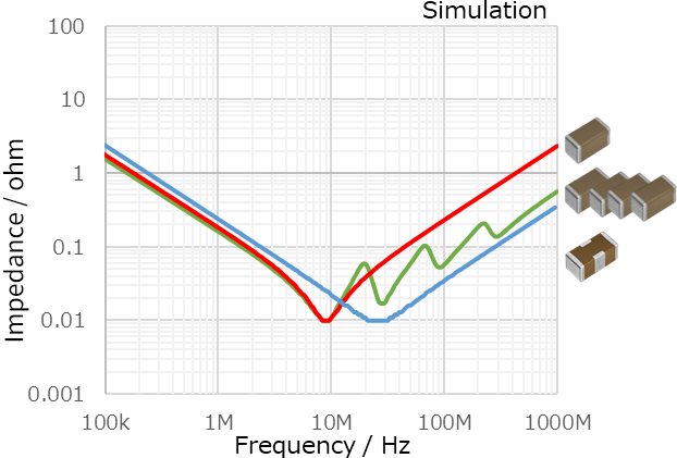
Figure 2 shows a comparison of the impedance-frequency characteristics and ESL values of TDK's 2-terminal MLCC, reverse geometry capacitor, and the 3-terminal feed-through filter.
The ESL value of the 3-terminal feed-through filter is lower compared to standard 2-terminal MLCCs and reverse geometry capacitors.
Applications and Expected Effects of 3-Terminal Feed-Through Filters
We will introduce solution examples for decoupling, filter, and DC/DC converter applications.
Solution Example for Decoupling Application
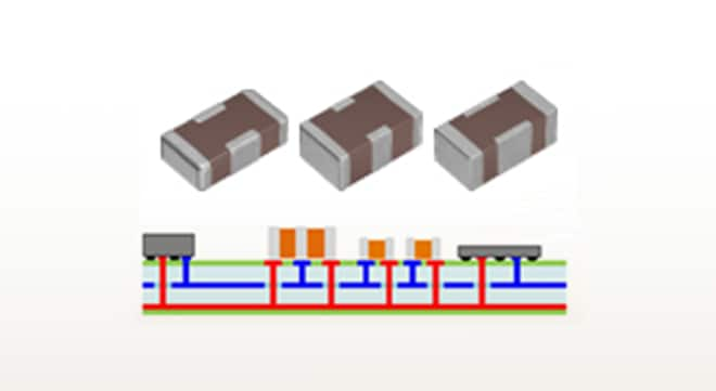
Voltage fluctuations in the power supply line can destabilize circuit operation and cause noise. To address this, a capacitor is inserted between the power supply line and ground, providing a temporary supply of current to suppress voltage fluctuations when the load changes suddenly.
This is known as decoupling, and the capacitors used for this purpose are called decoupling capacitors.
In recent years, the number of decoupling capacitors required to clear the target impedance has been increasing due to the higher power consumption, higher frequencies, and lower voltages associated with the miniaturization of SoCs. The YFF series 3-terminal feed-through filter, characterized by low ESL, is effective in reducing the number of capacitors needed when replacing conventional 2-terminal capacitors.
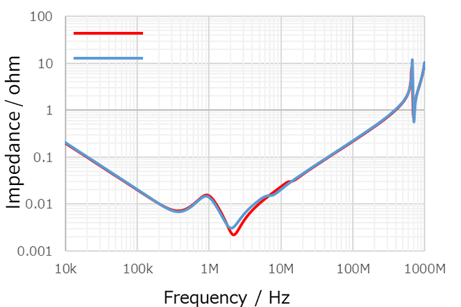
Impedance Comparison
1005mm(0402inch)/1uF (1pc) 2-terminal MLCC/1005mm(0402inch)
1uF/100nF/10nF/1nF (4pcs) 3-terminal feed-through filter/
1005mm(0402inch)/1µF (1pc)
The effect of reducing the number of
components can be observed.
We will demonstrate a reduction in the number of components using a 3-terminal feedthrough filter for decoupling applications using a PI simulation.
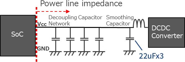
Here, we compare impedance data as seen from the SoC side.
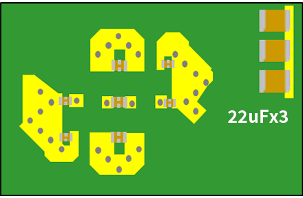
A common feature between the configurations before and after the proposal is that three 22uF MLCCs are connected to the DC/DC converter for smoothing.
Circuit Image
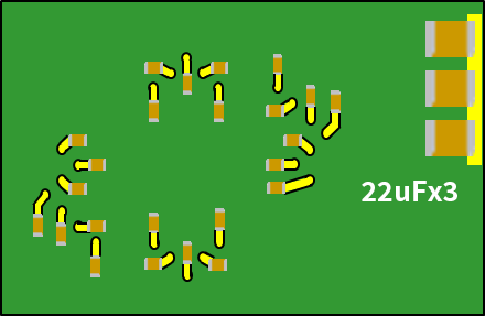
Current Configuration and TDK Proposed Configuration
Current configuration
2-terminal 1005mm (0402inch) x 24pcs
TDK proposed configuration
3-terminal 1608mm (0603inch) x 3pcs
3-terminal 1005mm (0402inch) x 4pcs
The current configuration and the TDK proposed configuration have almost the same characteristics.
Current configuration
| Terminal Structure | Product Type (mm/inch) |
Capacitance (uF) |
Quantity (pcs) |
Total Capacitance (uF) |
Mounting Area (mm2) |
|---|---|---|---|---|---|
| 2-terminal | 1005/0402 | 1 | 16 | 16 | 8 |
| 2-terminal | 1005/0402 | 0.1 | 8 | 0.8 | 4 |
| Current Configuration | 24 | 16.8 | 12 | ||
Number of components: -17pcs,
Mounting area: -51%
TDK proposed configuration
| Terminal Structure | Product Type (mm/inch) |
Capacitance (uF) |
Quantity (pcs) |
Total Capacitance (uF) |
Mounting Area (mm2) |
|---|---|---|---|---|---|
| 3-terminal | 1608/0603 | 4.7 | 3 | 14.1 | 3.84 |
| 3-terminal | 1005/0402 | 1 | 4 | 4 | 2 |
| TDK's Proposed Configuration | 7 | 18.1 | 5.84 | ||
Replacing a 2-terminal MLCC with a 3-terminal feed-through filter is expected to reduce the number of components. However, in actual circuits, the electrical elements of the board pattern are added, so the optimal number of decoupling capacitors may vary depending on the board layout.
TDK offers a free simulation service for replacing with a 3-terminal feed-through filter through PI simulation. For more details, please contact us.
Solution Example for Filter Application
With the recent increase in the operating frequency of power ICs, high-frequency noise has become a problem, causing abnormal operation of the set.
As a common countermeasure, a C-L-C π-type filter is configured on the power line.
However, incorporating a 3-terminal feed-through filter into the filter's capacitor can achieve a higher attenuation effect.
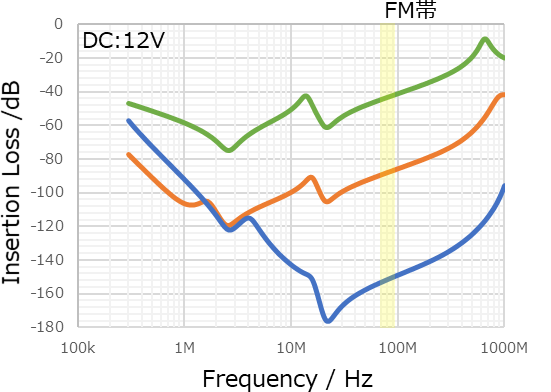
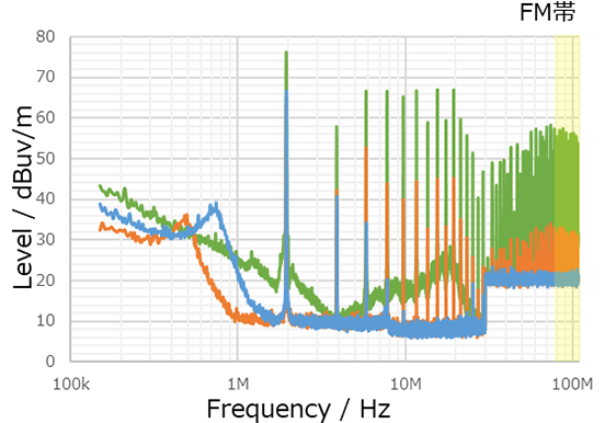
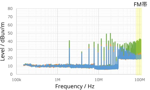
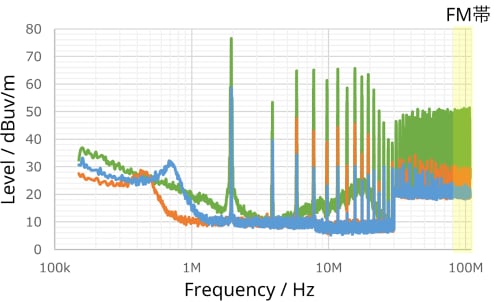
Figure 8 shows the results of transfer characteristics obtained through simulation, while Figure 9 presents the conducted noise (voltage method) measured in different noise modes using the actual DC/DC converter.
Please note that for the conducted noise voltage method in Figure 9, measurements were taken in all three configurations with our common mode filters installed as a common mode countermeasure.
Measurement Conditions and Circuit Diagram
| Π-type filter configuration | 1 | 2 | 3 |
|---|---|---|---|
| Wiring image | * No filter | ||
| C1 | - | 2-terminal capacitor, 3216mm(1206inch) , 4.7uF , 35V |
3-terminal feed-through filter 3216mm(1206inch) , 1uF , 100V , 6A YFF31AH2A105M Feed-through connection* |
| L1 | - | Ferrite bead 2.0×1.2mm, 220Ω at 100MHz, 3A |
Ferrite bead 2.0×1.2mm, 220Ω at 100MHz, 3A |
| C2 | - | 2-terminal capacitor, 3216mm(1206inch) , 4.7uF , 35V |
3-terminal feed-through filter 3216mm(1206inch) , 1uF , 100V , 6A YFF31AH2A105M Feed-through connection* |
*Please refer to the link below for Shunt-through connection.
About connection method
*The insertion loss includes the filter +
2-terminal MLCC 4.7uF + 2-terminal MLCC 0.1uF.
Insertion Loss Comparison
82MHz comparison
Configuration 1:-43dB
Configuration 2:-87dB
Configuration 3:-151dB
-44dB -64dBIncorporating a 3-terminal feed-through filter
achieves a high attenuation characteristic.
Configuration 1: No filter
Configuration 2: Capacitors (2-terminal)
Configuration 3: 3-terminal feed-through filter
Normal Mode
Normal mode noise is found to be high in
the evaluation environment of this DC/DC converter.
82MHz comparison
Configuration 1:54dBuV/m
Configuration 2:30dBuV/m
Configuration 3:20dBuV/m
-24dB -10dBEspecially in normal mode noise, incorporating a 3-terminal feed-through filter achieves a high noise reduction effect.
Configuration 1: No filter
Configuration 2: Capacitors (2-terminal)
Configuration 3: 3-terminal feedthrough filter
Common Mode
Common Mode + Normal Mode
By incorporating a 3-terminal feed-through filter into the filter, a high attenuation effect can be achieved over a wide frequency range.
Solution Examples for DC/DC Converter Applications
The switching frequency of the DC/DC converter has been increased from the conventional several hundred kHz to over 2 MHz,
as shown below, in order to reduce component size, obtain faster response, and avoid interference with the AM radio frequency band.
As a result, the frequencies of ripple noise and ringing noise are also increasing, creating a demand for broadband noise suppression measures up to the high frequency range of several hundred MHz.
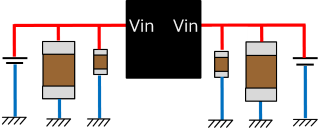
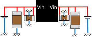
In this case study, we introduce the effects of using 3-terminal feedthrough filters on both the input and output sides of the DC/DC converter to suppress power fluctuations and reduce the number of components.
Example of a 3-terminal feed-through filter placed near the input terminal of a DC/DC converter
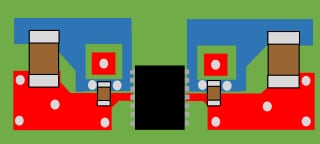
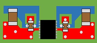
The input terminal of the DC/DC converter can generate significant high-frequency noise due to switching noise from wiring and IC parasitic components, leading to Nth-order harmonics from the fundamental frequency. This noise may radiate into external circuits. To address this, it is usually necessary to suppress the noise at its source, often by placing a small ceramic capacitor near the IC. Here, we present an example of a DC/DC converter using a 3-terminal feed-through filter. In this design, the 3-terminal feed-through filter is used as a noise countermeasure close to the IC. Both configurations include a 2-terminal MLCC 10uF capacitor placed on both sides of the input terminal.
| DC/DC converter conditions Input voltage: 5V Output voltage: 0.8V Switching frequency:2MHz Output current: 4A | ||
|---|---|---|
| Configuration | 2-terminal MLCC 1005mm/0402inch, 100nF,50V x 1pc *Shunt-through connection |
3-terminal feed-through Filter YFF18AC1A104M 1608mm/0603inch , 100nF ,10V x 1pc *Shunt-through connection |
| Wiring image | One side of power supply connected on the inner layer |
|
| Circuit diagram image | ||
*Please refer to the link below for Shunt-through connection.
About connection method
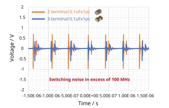
Voltage Waveform Comparison
2-terminal
0.1uFx1pc
1.64Vpp
3-terminal
0.1uFx1pc
0.92Vpp
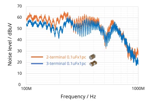
Conducted Noise Comparison
2-terminal
0.1uFx1pc
65dBuVmax
3-terminal
0.1uFx1pc
60dBuVmax
The 3-terminal is effective in suppressing voltage fluctuations and noise levels.
Example of a 3-terminal feed-through filter placed on the output side of a DC/DC converter
On the output side of a DC/DC converter, significant high-frequency noise can also be generated due to Nth harmonics from the fundamental frequency and parasitic components of wiring and ICs, which can radiate to external circuits.
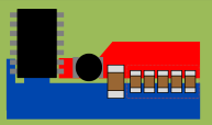
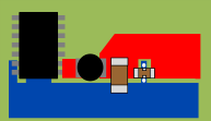
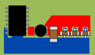
With the reduction in SoC voltage, the margin between maximum and minimum voltage has decreased. Additionally, as devices become more functional, more systems are becoming sensitive to high-frequency noise. In addition to addressing the issue on the SoC side, it is considered desirable to implement countermeasures on the power supply IC side, which is the source of the noise. Conventionally, an effective method for noise suppression was to arrange multiple 2-terminal MLCCs in stages. However, here we introduce an example where power supply fluctuations can be suppressed by using TDK's large-capacity 3-terminal feed-through filter. Both configurations include a 2-terminal MLCC 47uF capacitor as the output capacitor.
| Configuration | 2-terminal MLCC 1608mm/0603inch, 1uF, 16V x 5pcs |
3-terminal feed-through filter YFF18AC0G106M 1608mm/0603inch, 10uF, 4V x1 pc *Shunt-through connection |
3-terminal feed-through filter YFF18AC0G106M 1608mm/0603inch, 10uF, 4V x3 pcs *Shunt-through connection |
|---|---|---|---|
| DC/DC Converter conditions Input voltage: 5V Output voltage: 1.8V Switching frequency: 2MHz Output current: 2A | |||
| Wiring image | |||
| Circuit diagram image | |||
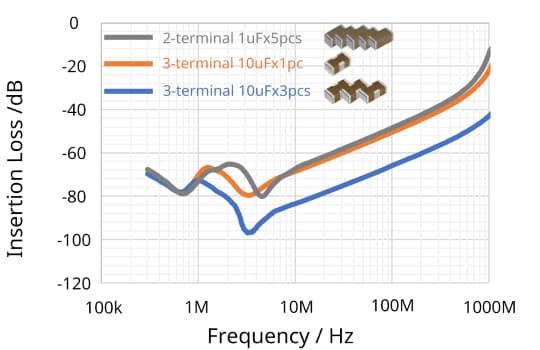
Insertion Loss Comparison
2-terminal
1uFx5pcs
-48.4dB
3-terminal
10uFx1pc
-50.5dB
3-terminal
10uFx3pcs
-65.9dB
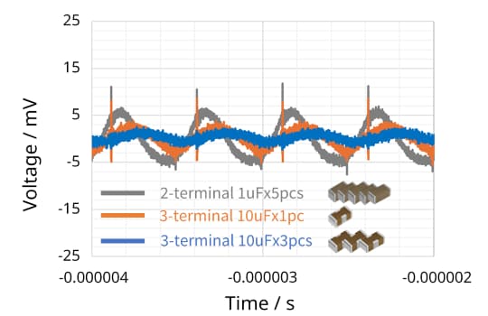
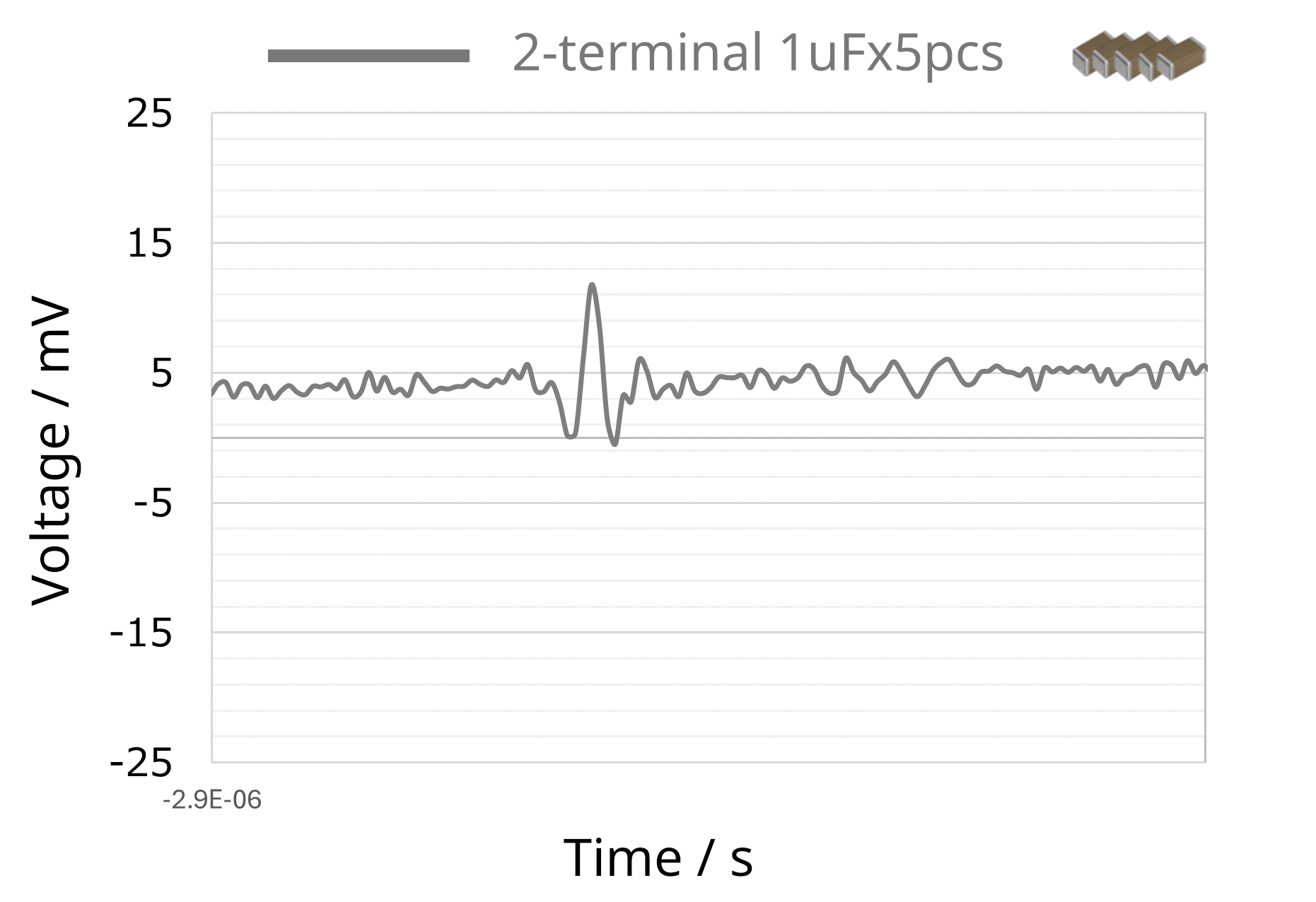
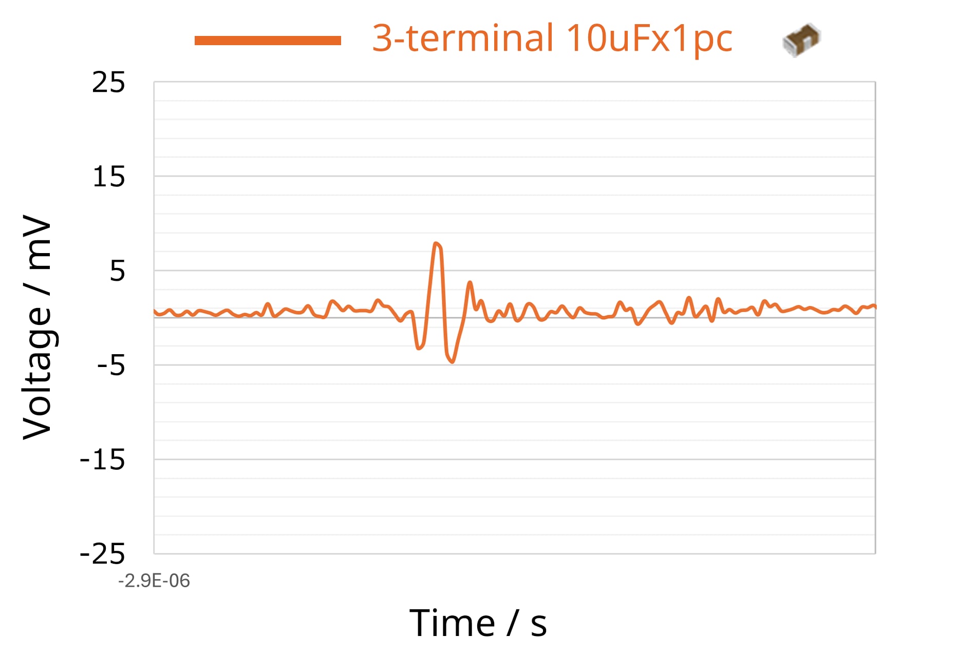
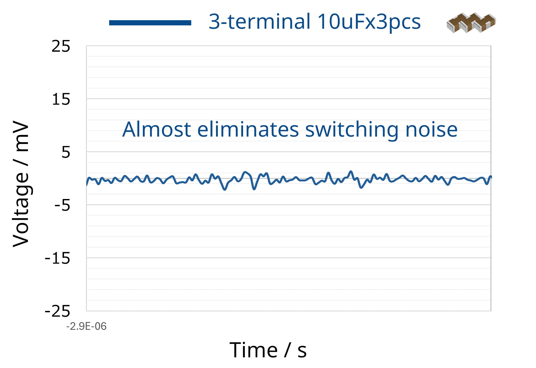
Voltage Waveform Comparison
2-terminal
1uFx5pcs
19mVpp
3-terminal
10uFx1pc
15mVpp
3-terminal
10uFx3pcs
5mVpp
The 3-terminals provide a high attenuation effect, making it effective for reducing the number of components and improving characteristics.
By connecting multiple 3-terminals in parallel, a high attenuation effect can be achieved.p
The voltage waveform focuses on switching noise.
By increasing the number of 3-terminal feed-through filters in parallel from one to three, switching noise was almost entirely eliminated.
Voltage Waveform Comparison
By incorporating TDK’s large-capacity 3-terminal feed-through filter, the amplitude level can be suppressed, effectively reducing the number of components.
Additionally, increasing the number of 3-terminal filters in parallel enhances the attenuation effect.
In this case, high-frequency switching noise was nearly eliminated with three parallel 3-terminal filters in Configuration 3.
Important Points to Fully Utilize the Characteristics of the 3-Terminal Feed-Through Filter
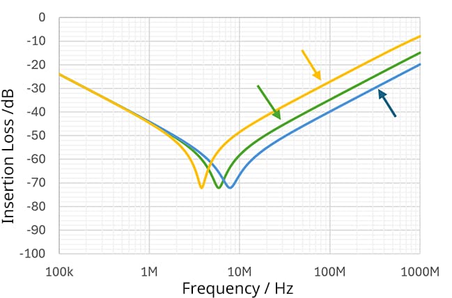
3-terminal feed-through filters are characterized by low ESL when used individually, but to fully utilize this feature, it is important to reduce parasitic components from ground patterns and vias.
Figure 15 shows the relationship between the length (depth) of the through-hole connecting the ground pattern and ground plane and the attenuation-frequency characteristics of the 3-terminal feed-through filter.
Simulations were performed to compare the following mounting conditions ① to ③.
When there are two through-holes at both ends of the ground pattern (condition ①) versus one through-hole on one side (condition ②), the configuration with two through-holes on both sides shows a greater attenuation. Additionally, with two through-holes on both sides and deeper through-holes (condition ③), the configuration with shorter (shallower) through-holes (condition ①) shows a greater attenuation.
Standalone 3-terminal feed-through filter characteristics YFF15AC0J105M (1005mm(0402inch)/6.3V/1uF)
Condition ① Condition ② Condition ③To fully utilize the characteristics of the 3-terminal feed-through filter, it is recommended to use multiple GND terminal through-holes and keep the through-hole length (depth) short.
Connection Methods
3-terminal Feed-through filters are typically used connected to the power line, and there are two connection methods.
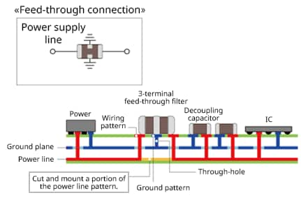
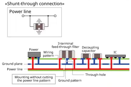
As shown in Figure 16, these methods are series connection (feed-through connection) and parallel connection (shunt-through connection).
The figure below illustrates each connection example. In this example, the first inner layer of the multilayer printed circuit board is the ground plane layer, and the second inner layer is the power line layer, with vias connecting each plane. For feed-through connection, a part of the power line pattern is cut and mounted, whereas for shunt-through connection, the power line pattern is is mounted without cutting.
Please refer to the table summarizing the characteristics and main applications of each connection method.
| Feed-through connection | Shunt-through connection | |
|---|---|---|
| Mounting method | Cut a portion of the line pattern where noise needs to be removed and insert the filter. |
Mount parallel (shunt) connection without cutting the line wiring pattern. |
| Main applications | Noise removal in high-frequency bands (filter applications) |
Suppression of IC voltage fluctuation (decoupling applications) |
| Advantages | High noise removal effectiveness over a wide band up to high frequencies. | No rated current limitation as almost no current flows through the chip. Easy to change the number of components even after board design, as the wiring pattern is not cut. |
| Disadvantages | Rated current limitation due to current flowing through the chip. Design changes are difficult because the power line/signal line is cut. |
Slightly higher ESL compared to feed-through connection. |
| Noise removal effectiveness |
◎ | 〇 |
| Effectively dissipates noise to GND as noise on the line must pass through the chip. |
Some noise passes through the power line, making noise removal less effective compared to feed-through connection. |
|
| Voltage fluctuation suppression effect |
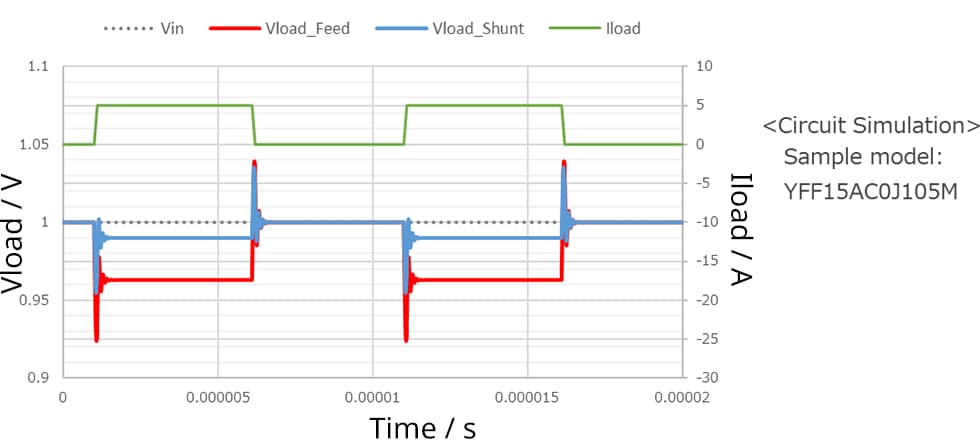
△ (Voltage drop occurs.) |
◎ (Smaller voltage drop.) |
Choose the appropriate mounting method according to the application.
In a feed-through connection, the voltage drop is greater than in a shunt-through connection, but the noise removal effect is higher. On the other hand, shunt-through connections can suppress voltage drops in the power line, making them suitable for low-voltage circuits. Please refer to the comparison table and select the connection method that best suits your application.
Conclusion
The YFF series 3-terminal feed-through filter is characterized by low ESL and high noise removal effectiveness. Due to its expanding lineup of high-capacity products, it is increasingly in demand for reducing component count and improving characteristics in filter applications, DC/DC converter applications, and decoupling applications
TDK offers products with a wide range of rated voltages and capacitances, enabling comprehensive product proposals from the power supply’s input side to the output side.
However, as demonstrated, the characteristics can vary depending on the board pattern and connection method. If you need support in using these products or are interested in PI simulation, please contact TDK.

