Ultra-Compact Metal Power Inductors: PLE Series

Using our original structural design and newly developed materials, the PLE Series achieves a wide range of inductance values through advanced thin-film processes.
This chapter explains the structure and characteristics and provides other useful information including applications.
About the PLE Series Ultra-Compact Metal Power Inductor
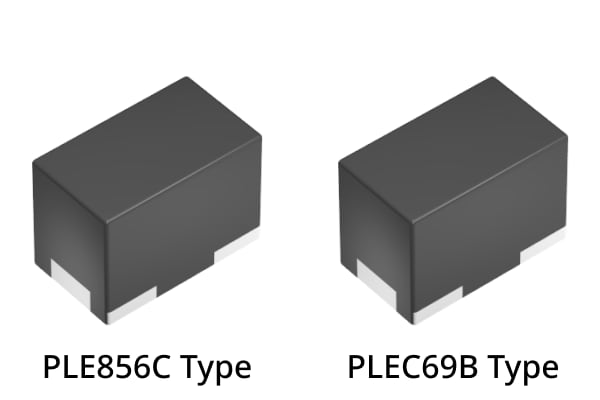
The overview of the PLE Series is presented in Figure 1.
| Type | PLE856C / PLEA67B / PLEC69B | PLEA85D |
|---|---|---|
| Product Overview |
| |
| Features |
| |
|
| |
| Applications | Wearable products (TWS, smart watches, hearing aids, AR glasses, etc.) Small power modules Communication modules (GNSS, Bluetooth, etc.)
| |
Structure of the PLE Series for Ultra-Compact High Inductance
Figure 2 illustrates the structure of the PLE Series.
The PLE series has an ultra-compact size, and offers a broad range of inductance values. This is achieved through the adoption of Thin-film HDD head technology and high precision lamination process.
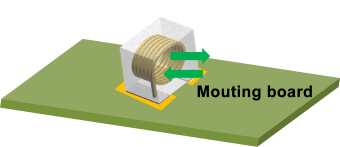
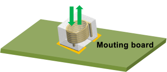
The lineup includes 3 types with distinct coil winding directions and configurations.
| Vertical coil winding type | Horizontal Coil Winding Type |
|---|---|
PLE856C Type Structure PLEA67B, PLEC69B Type Structure Terminal Electrode Terminal Electrode |
PLEA85D Type Structure Terminal Electrode |
The PLE Series, which uses a thin-film process optimized for ultra-compact power inductors, has the following features:
- The thin-film process enables high-precision lamination, minimizing variations.
- Achieves more than 2 turns per layer, allowing a lineup of high inductance despite its compact size.
The PLE Series utilizes newly developed metallic magnetic materials with high permeability and low loss, achieving low-loss and high-efficiency.
Figure 3 illustrates the thin-film process and the metallic magnetic materials used in the PLE Series.
Features of the PLE Series Optimized for Compact Wearable Devices
1. Two lineups with different coil winding directions
The PLE Series provides a fully shielded structure to suppress magnetic flux leakage, reducing noise impact in high-density mounting environments.
The direction of the generated magnetic flux varies depending on the coil winding direction, allowing the user to select the most suitable type for the application.
| type | PLE856C / PLEA67B / PLEC69B | PLEA85D |
|---|---|---|
| Direction of Magnetic Flux Leakage |
Flux leakage is horizontal to the board → Noise impact on the board surface is reduced |
Flux leakage is perpendicular to the board → Noise interference to peripheral components is reduced |
2. Product characteristics suitable for low-power devices
Wearable devices powered by small batteries require low power consumption, so Pulse Frequency Modulation (PFM) is used as the power supply drive method.
PFM has the advantage of lower power consumption due to lower DC bias current compared to Pulse Width Modulation (PWM), but has higher AC bias current. (Figure 5)
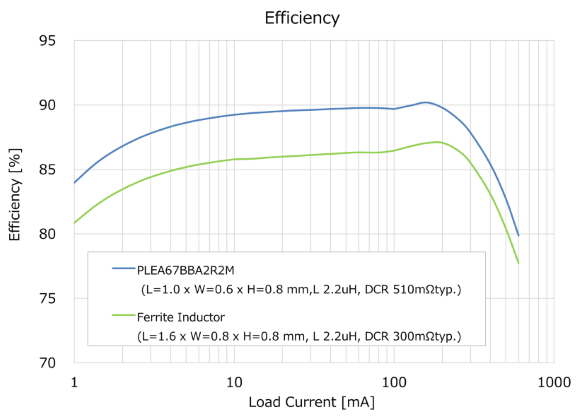
Therefore, the ACR characteristic becomes important, and by using Hi-Q, low-ACR inductors, it is possible to achieve high power supply efficiency. (Figure 6)
The PLE series, employing low-loss materials, achieves lower ACR. Consequently, it delivers higher power efficiency compared to larger-sized ferrite inductors.
PLE Series Applications
Typical applications of the PLE series are shown in the blue color blocks below in figure 7.
Due to its ultra-compact form factor, it is ideal for devices requiring high density mounting such as TWS and communication modules, therefore, contributing to smaller, lighter products and achieving higher efficiency performance.
PLE Series Lineup List
Click on the links below to view detailed information on the PLE series and purchase samples.
We are committed to expanding our lineup further to accommodate our customers’ diverse inductor needs.
| Type | Application | L Size ±0.1mm | W Size ±0.1mm | T Size max. | Inductance(μH) ±20% | DC Resistance (mΩ) max. | Rated Current Isat (A) max. |
|---|---|---|---|---|---|---|---|
| PLE856C | Commercial Grade | 0.8mm | 0.45mm | 0.65mm | 0.47 | 210 | 0.62 |
| 1.0 | 420 | 0.42 | |||||
| 1.5 | 520 | 0.33 | |||||
| PLEA67B | 1.0mm | 0.6mm | 0.8mm | 1.0 | 265 | 0.8 | |
| 2.2 | 650 | 0.5 | |||||
| 4.7 | 1080 | 0.3 | |||||
| PLEA85D | 1.0mm | 0.8mm | 0.55mm | 0.47 | 120 | 0.7 | |
| 1.0 | 300 | 0.6 | |||||
| 2.2 | 600 | 0.4 | |||||
| 3.3 | 1200 | 0.25 | |||||
| PLEC69B | 1.2mm | 0.6mm | 0.95mm | 10 | 1680 | 0.2 |
What are power inductors?
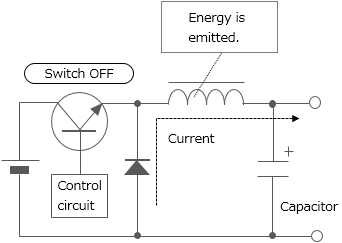
Power inductors are inductors used for power supply circuit such as DC-DC converters. They are also called power coils or power choke coil. One of the inductors' characteristics is that they store energy by self-induction function. Chopper type DC-DC converters use inductors having such characteristics with switching devices for voltage conversion (see Figure 9).
Depending on the processing method, inductors can be classified into multilayer type, thin-film type, and wire-wound type. Since wire-wound type permits large current to flow, most of the power inductors are wire-wound type. Various wound-type power inductor products with ferrite or soft magnetic metal core are offered. Recently, the multilayer type and thin-film type, with which reduction of size and thickness can be achieved, are being improved to allow for larger current.
The voltage is dropped to a desired level in accordance with the duty ratio (the ratio that indicates how long the switch is ON during the switching cycle) setting.
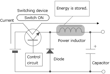
Switching repeated

