Power Inductor SPM Series

Table of contents
Product summary
The SPM series are the inductors that have the coils integrally molded with metallic magnetic powder. TDK offers a large selection of the SPM series inductors, including the low-profile SPM-LR series, the SPM-HZ and SPM-V series for automotive applications, and others.
| Commercial Grade | Automotive Grade | ||||||
|---|---|---|---|---|---|---|---|
| Series | SPM series Standard specifications |
SPM-CT series For high frequency use |
SPM-LR series Low-profile model |
SPM-XT series Large model |
|||
| Product summary | The inductors that have the coils integrally molded with magnetic powder. These inductors use Fe-base alloy powder to have high saturation characteristics, i.e. allowing for large current. |
The inductors that have the coils integrally molded with magnetic powder. These inductors use Fe-base alloy powder to have high saturation characteristics, i.e. allowing for large current. A wider operating temperature range than commercial grade products (DZ,V Series) |
|||||
| Features |
|
|
|||||
|
|
|
|
|
|
|
|
| Applications |
|
|
|
|
|
|
|
Product structures
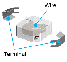
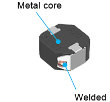
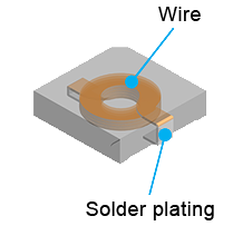
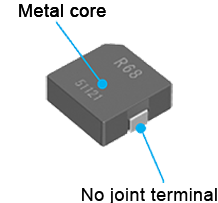
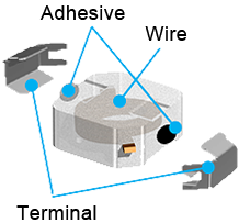
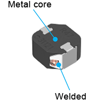
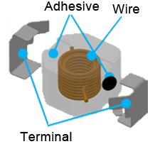
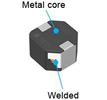
Figure 2 shows the structure of each SPM series. The integral mold structure and the welding method for connecting the wire and terminals achieves high reliability.
| Commercial Grade | Automotive Grade | ||||||
|---|---|---|---|---|---|---|---|
| Series | SPM | SPM-CT | SPM-LR | SPM-XT | SPM-HZ | SPM-DZ | SPM-V |
| Product structures | |||||||
Product features
Figure 3 shows the features of each SPM series.
| Series | SPM | SPM-CT | SPM-LR | SPM-XT | SPM-HZ | SPM-DZ | SPM-V |
|---|---|---|---|---|---|---|---|
| Appearance | |||||||
| Operating temperature range | -40 to 125°C (including self-temperature rise) |
-55 to 155°C (including self-temperature rise) |
|||||
| Magnetic material | Metallic magnetic material | ||||||
| Terminal electrode specifications | Metal terminal + plating | No joint terminal + plating | Metal terminal + plating | ||||
| Features | Commercial Grade |
Automotive Grade |
|||||
| Standard specifications | High frequency & High Q specifications | Low-profile specifications | Large current specifications | Supports use up to 125°C | Compact, low profile | High inductance High DC superimposition characteristics |
|
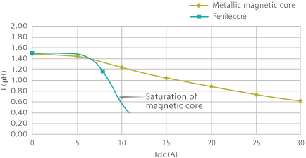
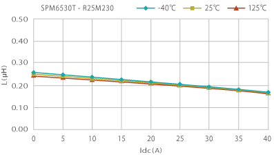
One of the remarkable features of the SPM series is that they are made with metallic magnetic core. Compared to ferrite cores, metallic magnetic cores have higher magnetic saturation density and better DC bias characteristic. In addition, since their Curie temperature is high, they show only a small change in characteristics with ambient temperature.
Core material characteristics of high magnetic saturation
Superior DC bias characteristic
Core material characteristics of high Curie temperature
Change in characteristics with ambient temperature is small.
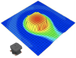
Since the SPM series inductors are made with wire-wound cores integrally molded with metallic magnetic powder, they do not have a core gap and the acoustic noise is reduced. Also, they have good shielding qualities and the magnetic flux leakage is small.
Core gapless (integral molding) for suppressing acoustic noise
Contributes to improve the set quality
Shielding structure for low magnetic flux leakage
Effective for reducing EMI
Vertical near magnetic field measurement result
List of products
Figure 8 shows the list of products by series and by shape. You can view the detailed information of the product or purchase a sample by clicking the type name.
- Commercial grade
- Automotive grade
| Size (mm) |
SPM | SPM-CT | SPM-LR | SPM-XT | SPM-HZ | SPM-DZ | SPM-V |
|---|---|---|---|---|---|---|---|
| 3mm sqr. |
3.2x3.0mm SPM3010-LR SPM3012-LR SPM3015-LR SPM3020-LR |
||||||
| 4mm sqr. |
4.2x4.0mm SPM4030 |
4.4x4.1mm SPM4010-LR SPM4012-LR SPM4015-LR SPM4020-LR |
4.2x4.0mm SPM4030-HZ |
SPM4020-DZ |
|||
| 5mm sqr. |
5.2x5.0mm SPM5030 |
5.4x5.1mm SPM5010-LR SPM5012-LR SPM5015-LR SPM5020-LR |
5.2x5.0mm SPM5030-HZ |
SPM5030VC |
|||
| 6mm sqr. |
7.1x6.5mm SPM6530 SPM6550 |
7.1x6.5mm SPM6550CT |
7.1x6.5mm SPM6530-HZ SPM6550-HZ |
SPM6545VT |
|||
| 7mm sqr. |
7.5x7.0mm SPM7054VC |
||||||
| 10mm sqr. |
10.7x10.0mm SPM10040 |
11.5x10.0mm SPM10040XT |
10.7x10.0mm SPM10040-HZ SPM10054-HZ |
10.5x10.0mm SPM10065VC |
|||
| 12mm sqr. |
12.6x13.0mm SPM12565XT |
13.0x12.5mm SPM12565VT |
What are power inductors?
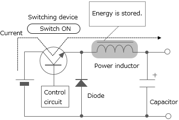
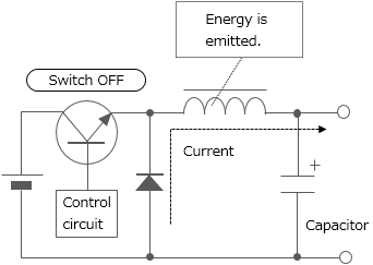
Power inductors are inductors used for power supply circuit such as DC-DC converters. They are also called power coils or power choke coil. One of the inductors' characteristics is that they store energy by self-induction function. Chopper type DC-DC converters use inductors having such characteristics with switching devices for voltage conversion (see Figure 9).
Depending on the processing method, inductors can be classified into multilayer type, thin-film type, and wire-wound type. Since wire-wound type permits large current to flow, most of the power inductors are wire-wound type. Various wound-type power inductor products with ferrite or soft magnetic metal core are offered. Recently, the multilayer type and thin-film type, with which reduction of size and thickness can be achieved, are being improved to allow for larger current.
The voltage is dropped to a desired level in accordance with the duty ratio (the ratio that indicates how long the switch is ON during the switching cycle) setting.
Switching
repeated
Contact Information
Related Links
Product Portal
Selection Guides
Products & Technologies
- Product Overview
- Ferrite Shield-Type Automotive Power Inductors
- Product Overview
- Power Inductor SPM Series
- Product Overview
- Power Inductor TFM Series
- Product Overview
- Power Inductor VLS Series
- Product Overview
- High frequency power inductors for automotive applications designed for outstanding reliability to reduce failure risks.


