- Capacitors >
- Multilayer Ceramic Chip Capacitors
A. TDK estimates Failure Rate using JIS C5003 standard and a combination of the number of life test failures, the total device-hours at stress temperature and voltage, temperature acceleration factor, and voltage acceleration factor. Failure rate (λ) is calculated with 60% confidence level.
•r = Number of failure
•Σ t = Total number of equivalent device hrs
•k = Coefficient for confidence level
(If r = 0, then use k = 0.917 only for 60%; otherwise use r x k, e.g. 2 x 1.55 for 2 failures)
| Observation | k Value | |
|---|---|---|
| 60% | 90% | |
| 0 failure | 0.917 | 2.30 |
| 1 failure | 2.02 | 3.89 |
| 2 failures | 1.55 | 2.66 |
| 3 failures | 1.39 | 2.23 |
| 4 failures | 1.31 | 2.00 |
| 5 failures | 1.26 | 1.85 |
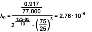
For calculating Failure Rate with operating condition (λ0), the below equation is used:
Example:
To calculate the Failure of a CGA2B3X7R1H104K capacitor, assuming the customer uses the capacitor at 85 degree Celsius and half the rated voltage (25V) @ 60% confidence level with life test conditions @ 125°C, 1.5xRV, and 77pcs for 1,000 hours:
One unit of FIT = 1 x 10⁻⁹:
MTBF/MTTF is the reciprocal of FIT. Below is the equation to illustrate this.
Based on this formula, lower failure rate would equate to higher mean time to failure. In regard to the previous example, MTBF would equal 4140.9 years.
>>Multilayer Ceramic Chip Capacitors Product site
>>MLCC with Dipped Radial Lead Product site
For any other product-related questions or inquiries, please contact us throughone of our sales representatives or this website.


