Application Note Automotive LED Lighting
As the electrification of automobiles advances, power consumption control is becoming an increasingly important factor. LED Lighting Technology design reduces power consumption, increases lifecycle, offers design freedom and overall control. It is now used in Automotive functions including headlights and interior lighting. The TDK Group offers an extensive lineup of power inductors for use in LED drivers optimized for different systems including step-up, step-down, and step-up/step-down types.Contents
Main circuit Types used in LED drivers
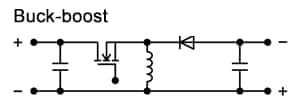
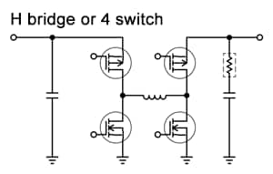
Constant-current circuits are needed to operate LEDs. DC-DC converters are essential for supplying stable electric power from variable battery power. The DC-DC converters (LED drivers) commonly used are categorized into step-up type, step-down type, and step-up/step-down types depending upon the number of LEDs and system selected. Suppose the battery voltage decreases to about 6 V, the typical forward voltage for one general white LED is only 3.5 V, a step-down type converter would be used. If two to four LEDs are connected in series a step-up/step-down type is used. When five or more LEDs are connected in series, a step-up type is used. In a system with multiple functions including headlights, daytime running lights, and turn signals these circuits are then used in combination.
| Circuit Type | Circuit Diagram | ||
|---|---|---|---|
| Step-down type | |||
| Step-up type | |||
| Step-up/step-down type | |||
Circuit Types for high-performance LED headlights
Typically, high-performance LED headlights use variable light distribution functions to change the range of illumination and vary the brightness.
In order to vary the brightness and range of illumination, multiple LEDs are used. The luminance of each LED is then adjusted to achieve the brightness and range of illumination.
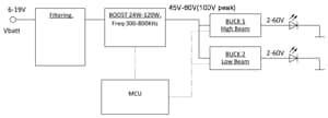
Figure 1 shows a basic circuit structure. The battery voltage is increased to an approximate 40 - 60V and a buck converter supplies current to the LED.
| or | + |
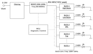
Multiple LEDs are connected in series and parallel behind the buck converter (Figure 2). The current that flows to each LED is individually adjusted to change the brightness, and in extreme cases, only a single LED is illuminated and voltage close to 60 V is applied to the output inductor of the buck converter. As a result, when used in this application, a higher comparative inductance (e.g., 100 μH) is selected. The smoothing capacitor used with the boost converter in the front end needs to maintain the current against sudden transitions in order to change the illumination range instantaneously. Typically the required range of capacitance for this smoothing capacitor is 1µF to 10µF at a withstanding voltage of 100 V.
Drive circuits for LED headlights and TDK inductors
Single lamp types use a single converter and a step-up/step-down or step-up type driver. They are used for single-function vehicle exterior lighting, interior lighting, infotainment systems, etc.
Multi-beam types use two converters, a step-up circuit in the front end and a step-down circuit or constant current circuit in the back end. For vehicle exterior illumination, in the case of headlights, this structure is used to switch between high beams and low beams. Also, daytime running lights (DRL) can be added.
Adaptive front lighting systems also use two converters, a step-up circuit in the front end and a step-down circuit or constant current circuit in the back end. They are used for LED headlight systems including main headlights, DRL, turn signal lights, and so on.
| Filtering | BOOST (Vbat to ~40-60V) | BUCK (40/60V TO 3-60V) | |||
|---|---|---|---|---|---|
| Series | SPMseries | SPMseries | CLFseries | SPMseries | CLFseries |
| Exterior | |||||
| Features |
|
|
|
||
Boost converter circuit examples
Single lamp type LED headlight functions are simple and are used to switch between high and low beams.
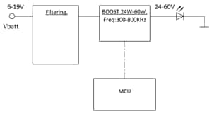
In this case, a step-up (boost) converter of about 15 W to 30 W is used. A representative circuit structure is shown below.
The output voltage is determined according to the number of LEDs in series and is in the range of about 20 V to 30 V. In the case of a step-up circuit, switching losses are high compared to a step-down circuit, and increasing the frequency is difficult. The most common frequency range is between 200 to 400 khz.
LEDs for DRL and compact lighting applications (low power)
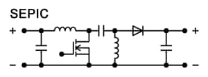
Systems with relatively low power including DRLs, interior illumination, back lighting, and turn signal lights use a constant current circuit or step-up/step-down circuit. The step-up/step-down circuit used in LED circuits commonly make use of SEPIC circuits.
Figure 4 shows a SEPIC circuit example. Two inductors (L1 and L2) a DC cut capacitor (C1) are used. The output is controlled in the same manner as a conventional step-up/step-down converter and is determined using the following formula. In the case of a conventional step-up/step-down converter (Circuit B), the input and output polarities are reversed, but in the case of a SEPIC circuit, the polarities are the same. The fundamental relationship formula is as shown below, and the output voltage is the same as the capacitor (C1) input voltage.
??=??? ?/(1−?) (D:duty)
??1=???
??2=??1
IL2ave=IL1ave(1−?)/?
Based on the above relationship formula, theoretically the voltages applied to L1 and L2 (VL1 and VL2) are the same and a combination dual coil with a 1:1 winding ratio (Circuit C) can be used. In cases where a dual coil is used, the load on the core is double that compared to when a single coil is used, and an inductor with low core loss and high DC superposition is needed. The B82477D* series of TDK inductor products is suitable. These products use low-loss materials in the DR core and control for thermal generation area.
| B82477D Series | |
|---|---|
| Exterior | |
| Spec |
|
| Features |
|


