Tech Library
Application & Cases
[ ]
Application Note

Failure Modes and Countermeasures in Actual Use of NTC Thermistors

NTC (Negative Temperature Coefficient) thermistors are thermally sensitive semiconductor resistors which show a decrease in resistance as temperature increases, and its rate of change is extremely large.

Its main applications include temperature sensing in electronic equipment and temperature compensation for module products.

However, if the user misuses the product, it may not function properly and, in the worst case, this may cause malfunctions.

This page introduces the causes and countermeasures for ”cracks” and ”melting of ceramics” as failure modes caused by improper use of NTC thermistors.

Outline

Figure 1: Failure Mode and Cause
Video 1: Overview Video
Video Player is loading.
Current Time 0:00
Duration 7:00
Loaded: 2.36%
Stream Type LIVE
Remaining Time 7:00
 
1x
  • Chapters
  • descriptions off, selected
  • captions off, selected
  • en (Main), selected

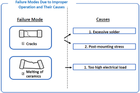
Failure Mode (1) <Cracks>

Figure 2: Failure Mode 1 <Cracks>

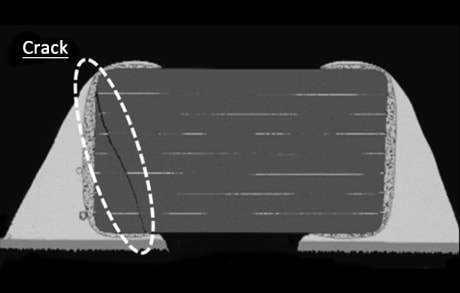
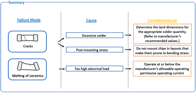
The most common failure mode is 'cracking'.
Cracks are sometimes caused by mechanical stress during or after mounting on the board. Two common causes are "Excessive solder" and "post-mounting stress".

1st Cause: Excessive solder

Figure 3: Excessive solder

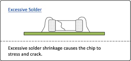
When mounting NTC thermistors on boards, Excessive solder may cause cracking.

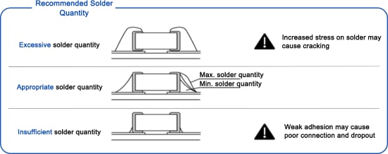
As the solder quantity increases, the stress on the NTC thermistor increases.
This is due to bending stress caused by the solder, which may lead to cracking when the applied solder is too much.
However, if there is too little solder, there is a risk of poor connection or chip or the joint may be unstable and chip dropout.
Thereefore, it is important to apply an appropriate quantity of solder.

Figure4: Recommended Solder Quantity

Countermeasures

When designing the land pattern on the board, set the pattern shape and dimensions to ensure appropriate application of the solder.

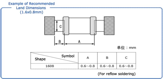
Please use the data sheets and brochures(catalogs) available on our website to check the recommended land pattern dimensions for your product.
By designing the land pattern according to the recommended dimensions, you can avoid excessive or insufficient solder quantity.

For example, for our 1.6 x 0.8 mm NTC thermistor, the following land pattern dimensions are recommended:

Figure 5: Example of Recommended Land Dimensions

2nd Cause: Post-mounting stress

Figure 6: Post-mounting Stress

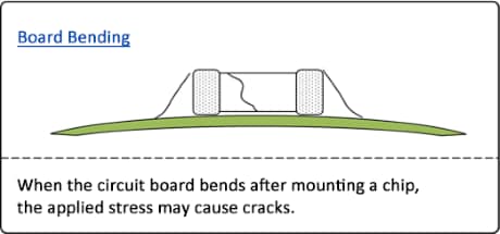
If an NTC thermistor is solder-mounted on a mounting board that has been deformed due to a split plate or screw, cracks may occur due to stress.
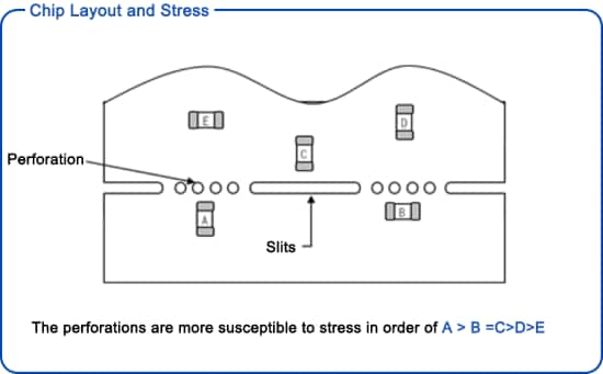
In particular, it is important to note that the NTC thermistor is more prone to high amount of stress around the split plate.

Countermeasures

This stress due to bending of the board varies greatly depending on the placement of components on the board where the NTC thermistor is mounted.

Figure 7: Board Bending Stress and Chip Layout

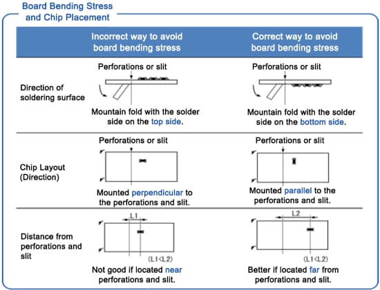
As an example, stress can be reduced by placing the chip parallel to the split-plate surface rather than perpendicular to it. Also, the further away it is from the split plate section, the more stress is reduced.

Figure 8: Chip Layout and Stresses

The risk of cracking can be greatly reduced by designing the board so that the NTC thermistor is positioned against bending stress.
In addition, even without split plates, cracking may still occur due to deflection stress caused by bending of the board, dropping, or impact.
After mounting the NTC thermistor, please be careful not to apply external stress to the board.

Failure Mode (2) <Melting of ceramics>

Figure 9: Failure Mode (2) <Melting of ceramics>

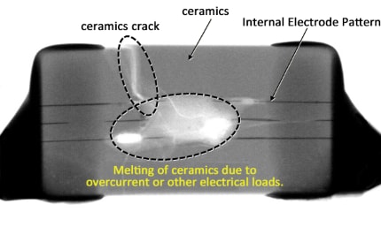
Since NTC thermistors are temperature-sensing devices, self-heating should be reduced as much as possible in order to accurately detect temperature.
However, there are cases where the thermistor’s temperature exceeds its melting point, which could melt the board if excessive electrical load continues to be applied.

1st Cause: Overcurrent

As mentioned earlier, one of the causes of ceramics melting is the application of large electrical load to the NTC thermistor.

Figure 10: Self-heating and Temperature Inaccuracy due to Overcurrent

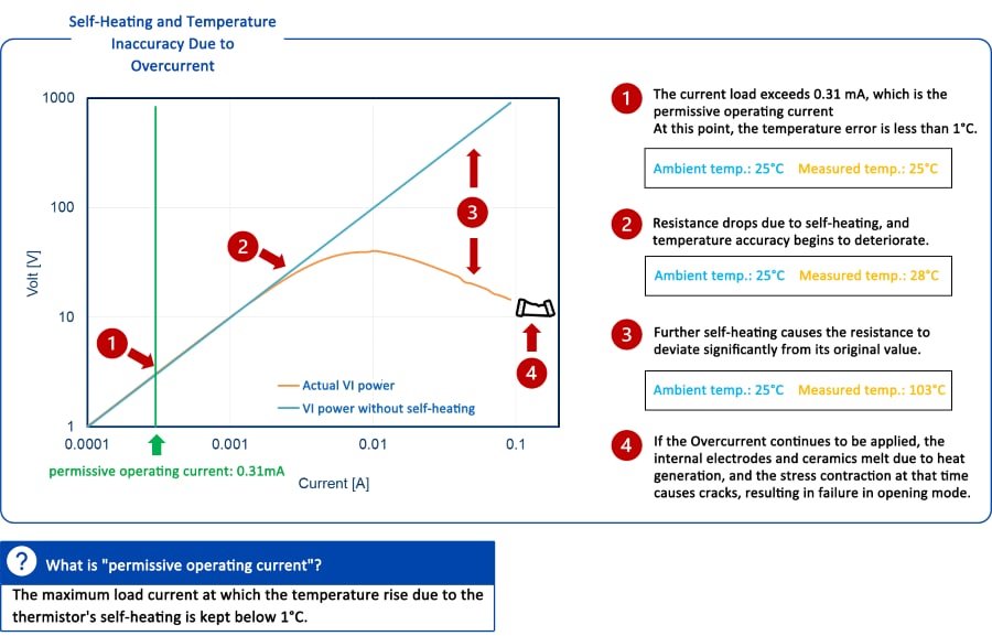
Since NTC thermistors have negative electrical resistance in relation to temperature, their resistance decreases due to self-heating that occurs when excessive current flows through them.

Due to these electrical characteristics, continuous overcurrents that greatly exceed the allowable operating current can lead to "over heat," in which a decrease in resistance due to self-heating alternates with an increase in current due to the decrease in resistance. Then, if the internal temperature of the element exceeds the melting point of the ceramics, the element will melt. 

Video 2: NTC Thermistor Melting due to Overcurrent
Video Player is loading.
Current Time 0:00
Duration 0:16
Loaded: 0.00%
Stream Type LIVE
Remaining Time 0:16
 
1x
  • Chapters
  • descriptions off, selected
  • captions off, selected
  • en (Main), selected

    Countermeasures

    Make sure the components and design circuits do not apply current exceeding the permissive operating current.
    For example, for our 1.0 x 0.5 mm NTC thermistors, the permissive operating current is specified as 0.03 to 0.21 mA.
    (Note: In actual use, this varies depending on the land pattern, solder quantity, board material, etc.)
    The permissive operating current is specified for each part number, and should be in accordance with the specified value of each NTC thermistor manufacturer.

    As a countermeasure against overcurrent, a voltage divider circuit using a fixed resistor is effective.

    Examples of circuits for each application are shown in the following pages for your reference.

    We also have an online tool where you can select the optimum product and sensing circuit using our NTC thermistors.
    You can use this tool to find the best solution to your product.

    Summary

    This page summarizes the NTC thermistor's failure modes, mainly due to misuse, and their countermeasures.

    Figure 11: Summary

    NTC thermistor failures due to improper use are not limited to those introduced here.
    Detailed handling precautions are described in our product catalogs and delivery specifications.
    We hope that you will find this information useful for the safe use and application of NTC thermistors.

    Product List

    Commercial Grade
    Product Image Series, Types L×W size Height Nominal Resistance [@25℃] B value
    [25/50℃]
    B value
    [25/85℃]
    B value
    [25/100℃]
    Product Catalog RoHS Certificate REACH Certificate Part No. Lists
    NTCG04

    NTCG06

    NTCG10

    NTCG16

    NTCG20
    0.4x0.2mm
    [EIA 01005]
    0.6x0.3mm
    [EIA 0201]
    1.0x0.5mm
    [EIA 0402]
    1.6x0.8mm
    [EIA 0603]
    2.0x1.2mm
    [EIA 0805]
    0.2mm

    0.3mm

    0.5mm

    0.8mm

    1.0mm
    10kΩ~470kΩ

    40Ω~100kΩ

    22Ω~470kΩ

    30Ω~1MΩ

    470Ω~150kΩ
    3380~4250K

    3244~4485K

    3244~4661K

    3244~4661K

    3060~4085K
    3413~4293K

    3250~4550K

    3250~4750K

    3250~4750K

    3150~4150K
    3445~4306K

    3253~4327K

    3251~4780K

    3251~4780K

    3670~4172K
    pdf
    862KB
    pdf
    39KB
    pdf
    103KB
    Part No. Lists
    B57*V2
    1.0×0.5mm
    [EIA 0402]
    1.6×0.8mm
    [EIA 0603]
    2.0×1.25mm
    [EIA 0805]
    0.6mm max.

    0.9mm max.

    1.3mm max.
    4.7kΩ~100kΩ

    1.0kΩ~470kΩ

    1.0Ω~470kΩ
    3940~4250K

    3940~4386K

    3940~4386K
    3980~4311K

    3980~4455K

    3980~4455K
    4000K±3%~4334K±1%

    4000K±3%~4480K±3%K

    4000K±3%~4480K±3%
    pdf
    421KB
    pdf
    209KB
    pdf
    209KB
    Part No. Lists
    B57621C5
    3.2×1.6mm
    [EIA 1206]
    1.3mm max.
    1.0kΩ~10kΩ
    3420~3470K
    3440~3510K
    3450K±3%~3530K±3%
    pdf
    532KB
    Part No. Lists
    Product Image Series, Types L×W size Height Nominal Resistance [@25℃] B value
    [25/50℃]
    B value
    [25/85℃]
    B value
    [25/100℃]
    Product Catalog RoHS Certificate REACH Certificate Part No. Lists
    NTCG04

    NTCG06

    NTCG10

    NTCG16

    NTCG20
    0.4x0.2mm
    [EIA 01005]
    0.6x0.3mm
    [EIA 0201]
    1.0x0.5mm
    [EIA 0402]
    1.6x0.8mm
    [EIA 0603]
    2.0x1.2mm
    [EIA 0805]
    0.2mm

    0.3mm

    0.5mm

    0.8mm

    1.0mm
    10kΩ~470kΩ

    40Ω~100kΩ

    22Ω~470kΩ

    30Ω~1MΩ

    470Ω~150kΩ
    3380~4250K

    3244~4485K

    3244~4661K

    3244~4661K

    3060~4085K
    3413~4293K

    3250~4550K

    3250~4750K

    3250~4750K

    3150~4150K
    3445~4306K

    3253~4327K

    3251~4780K

    3251~4780K

    3670~4172K
    pdf
    862KB
    pdf
    39KB
    pdf
    103KB
    Part No. Lists
    B57*V2
    1.0×0.5mm
    [EIA 0402]
    1.6×0.8mm
    [EIA 0603]
    2.0×1.25mm
    [EIA 0805]
    0.6mm max.

    0.9mm max.

    1.3mm max.
    4.7kΩ~100kΩ

    1.0kΩ~470kΩ

    1.0Ω~470kΩ
    3940~4250K

    3940~4386K

    3940~4386K
    3980~4311K

    3980~4455K

    3980~4455K
    4000K±3%~4334K±1%

    4000K±3%~4480K±3%K

    4000K±3%~4480K±3%
    pdf
    421KB
    pdf
    209KB
    pdf
    209KB
    Part No. Lists
    B57621C5
    3.2×1.6mm
    [EIA 1206]
    1.3mm max.
    1.0kΩ~10kΩ
    3420~3470K
    3440~3510K
    3450K±3%~3530K±3%
    pdf
    532KB
    pdf
    209KB
    pdf
    209KB
    Part No. Lists
    Automotive Grade
    Product Image Series, Types L×W size Height Nominal Resistance [@25℃] B value
    [25/50℃]
    B value
    [25/85℃]
    B value
    [25/100℃]
    Product Catalog RoHS Certificate REACH Certificate Part No. Lists
    NTCGS06

    NTCGS10

    NTCGS16
    0.6×0.3mm
    [EIA 0201]
    1.0×0.5mm
    [EIA 0402]
    1.6×0.8mm
    [EIA 0603]
    0.3mm

    0.5mm

    0.8mm
    10kΩ

    10kΩ

    10kΩ
    3380K

    3380K

    3380K
    3435K

    3435K

    3435K
    3453K

    3453K

    3453K
    pdf
    729KB
    pdf
    39KB
    pdf
    98KB
    Part No. Lists
    NTCG06

    NTCG10

    NTCG16

    NTCG20
    0.6×0.3mm
    [EIA 0201]
    1.0×0.5mm
    [EIA 0402]
    1.6×0.8mm
    [EIA 0603]
    2.0×1.2mm
    [EIA 0805]
    0.3mm

    0.5mm

    0.8mm

    1.0mm
    10kΩ~100kΩ

    10kΩ~150kΩ

    100Ω~150kΩ

    10kΩ~100kΩ
    3380~4250K

    3380~4533K

    3244~4632K

    3590~4085K
    3435~4308K

    3435~4550K

    3250~4720K

    3590~4085K
    3453~4327K

    3453~4573K

    3251~4749K

    3670~4172K
    pdf
    455KB
    Part No. Lists
    NTCSP10

    NTCSP16
    1.0×0.5mm
    [EIA0402]
    1.6×0.8mm
    [EIA0603]
    0.5mm

    0.8mm
    10kΩ~100kΩ

    10kΩ~100kΩ
    3380~4419K

    3380~4419K
    3435~4485K

    3435~4485K
    3453~4509K

    3453~4509K
    pdf
    289KB
    Part No. Lists
    B57*V5
    1.0×0.5mm
    [EIA 0402]
    1.6×0.8mm
    [EIA 0603]
    2.0×1.25mm
    [EIA 0805]
    0.6mm max.

    0.9mm max.

    1.3mm max.
    4.7kΩ~100kΩ

    10kΩ~100kΩ

    4.7kΩ~100kΩ
    3940~4250K

    3366~4386K

    3590~4386K
    3980~4311K

    3419~4455K

    3635~4455K
    4000K±3%~4334K±1%

    3439K±0.5%~4480K±3%K

    3650K±3%~4480K±3%
    pdf
    445KB
    pdf
    209KB
    pdf
    209KB
    Part No. Lists
    B57621C5502H062
    3.2×1.6mm
    [EIA 1206]
    1.3mm max.
    5.0kΩ
    3375K
    3420K
    3455K
    pdf
    299KB
    Part No. Lists
    B57*V6/C6 Soft termination
    1.6×0.8mm
    [EIA 0603]
    3.2×1.6mm
    [EIA 1206]
    0.9mm max.

    1.3mm max.
    10kΩ~47kΩ

    5kΩ
    3380~4050K

    3375K
    3435~4108K

    3420K
    3455K±1%~4131K±1.5%

    3455K±2%
    pdf
    455KB
    Part No. Lists
    Product Image Series, Types L×W size Height Nominal Resistance [@25℃] B value
    [25/50℃]
    B value
    [25/85℃]
    B value
    [25/100℃]
    Product Catalog RoHS Certificate REACH Certificate Part No. Lists
    NTCGS06

    NTCGS10

    NTCGS16
    0.6×0.3mm
    [EIA 0201]
    1.0×0.5mm
    [EIA 0402]
    1.6×0.8mm
    [EIA 0603]
    0.3mm

    0.5mm

    0.8mm
    10kΩ

    10kΩ

    10kΩ
    3380K

    3380K

    3380K
    3435K

    3435K

    3435K
    3453K

    3453K

    3453K
    pdf
    729KB
    pdf
    39KB
    pdf
    98KB
    Part No. Lists
    NTCG06

    NTCG10

    NTCG16

    NTCG20
    0.6×0.3mm
    [EIA 0201]
    1.0×0.5mm
    [EIA 0402]
    1.6×0.8mm
    [EIA 0603]
    2.0×1.2mm
    [EIA 0805]
    0.3mm

    0.5mm

    0.8mm

    1.0mm
    10kΩ~100kΩ

    10kΩ~150kΩ

    100Ω~150kΩ

    10kΩ~100kΩ
    3380~4250K

    3380~4533K

    3244~4632K

    3590~4085K
    3435~4308K

    3435~4550K

    3250~4720K

    3590~4085K
    3453~4327K

    3453~4573K

    3251~4749K

    3670~4172K
    pdf
    455KB
    pdf
    39KB
    pdf
    98KB
    Part No. Lists
    NTCSP10

    NTCSP16
    1.0×0.5mm
    [EIA0402]
    1.6×0.8mm
    [EIA0603]
    0.5mm

    0.8mm
    10kΩ~100kΩ

    10kΩ~100kΩ
    3380~4419K

    3380~4419K
    3435~4485K

    3435~4485K
    3453~4509K

    3453~4509K
    pdf
    289KB
    pdf
    39KB
    pdf
    98KB
    Part No. Lists
    B57*V5
    1.0×0.5mm
    [EIA 0402]
    1.6×0.8mm
    [EIA 0603]
    2.0×1.25mm
    [EIA 0805]
    0.6mm max.

    0.9mm max.

    1.3mm max.
    4.7kΩ~100kΩ

    10kΩ~100kΩ

    4.7kΩ~100kΩ
    3940~4250K

    3366~4386K

    3590~4386K
    3980~4311K

    3419~4455K

    3635~4455K
    4000K±3%~4334K±1%

    3439K±0.5%~4480K±3%K

    3650K±3%~4480K±3%
    pdf
    445KB
    pdf
    209KB
    pdf
    209KB
    Part No. Lists
    B57621C5502H062
    3.2×1.6mm
    [EIA 1206]
    1.3mm max.
    5.0kΩ
    3375K
    3420K
    3455K
    pdf
    299KB
    pdf
    209KB
    pdf
    209KB
    Part No. Lists
    B57*V6/C6 Soft termination
    1.6×0.8mm
    [EIA 0603]
    3.2×1.6mm
    [EIA 1206]
    0.9mm max.

    1.3mm max.
    10kΩ~47kΩ

    5kΩ
    3380~4050K

    3375K
    3435~4108K

    3420K
    3455K±1%~4131K±1.5%

    3455K±2%
    pdf
    455KB
    pdf
    209KB
    pdf
    209KB
    Part No. Lists