Solution GuideEnsuring communication quality and filtering suitable for PoC (Power over Coax)
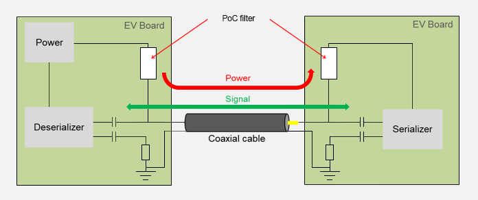
With the increasing speed and sophistication of interfaces in cars, the PoC (Power over Coax) approach is gaining in popularity, as it allows superimposing signals and power in one coaxial cable, for example for LVDS based automotive camera systems. A PoC filter consisting of one or more inductors and chip beads is used on the circuit side to separate the signal and the power supply current. This is important in terms of maintaining communication quality. The PoC filter therefore requires inductors that realize high impedance for AC components over a wide bandwidth range from low to high frequencies.Content
Importance of maintaining communication quality with PoC (Power over Coax)
The PoC approach combines communication signals and power supply within a single coaxial cable. To keep the signal and power separate, a PoC filter that uses inductors and chip beads so that the signal does not pass through the power supply line is required.
If the impedance characteristic of the PoC filter inductors does not satisfy the system requirements, communication quality will be degraded, which may result in malfunction and safety problems.
Example
The PoC filter does not provide sufficient transmission quality and resistance against noise such as EMS, leading to communication errors that may prevent display of the image from the camera, thereby disrupting normal operation (see Fig. 1).
Product structure for realizing wide-band high impedance
To ensure the communication quality outlined in the preceding section, the PoC must be resistant to noise. This in turns requires inductors with high impedance for AC components over the entire bandwidth range from low to high frequencies. The high impedance requirement applies to communication frequency bands ranging from several MHz to several hundred MHz (sometimes up to several GHz).
With a conventional multilayer inductor, it is necessary to connect multiple coils in series because high impedance can otherwise not be realized over a wide frequency range (Fig. 2).
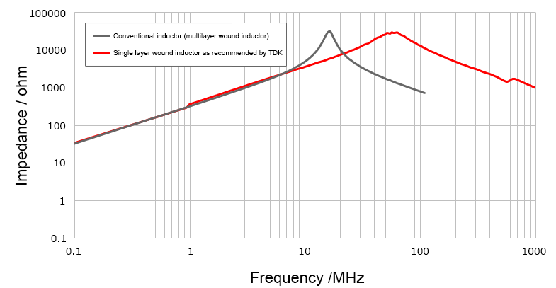
Conventional multilayer inductors also have a problem in that a higher number of windings is required to obtain high impedance, which results in increased DC resistance. Purpose-designed PoC filter inductors from TDK adopt the single layer coil structure. Consequently, parasitic capacitance is kept low and the resonant frequency is higher compared to inductors with a multilayer winding structure (Fig. 3).
Constantly high impedance is therefore achieved over a wider frequency range (Fig. 4).
At the same time, the inductors are designed to realize extremely low DC resistance.
Compared to conventional filter configurations, the use of inductors specifically designed for PoC filters allows a reduction in the parts count, making it possible to achieve the same impedance while realizing a smaller mounting footprint.
The following section explains the eye pattern waveform which is a crucial consideration in the selection of inductors and chip beads for enabling the superimposition of communication signals and the power supply line.
When configuring a PoC filter with multilayer wound inductors,
multiple inductors are required to achieve high inductance from the low frequency side to the high frequency side.
The same high impedance is achieved over a wider frequency range with the inductors for PoC filter use.
Eye pattern waveform and selection of inductors and chip beads
To evaluate PoC filter characteristics, it is useful to compare the eye pattern waveform obtained with a conventional inductor and the PoC filter inductor from TDK.
| PoC filter configuration | Inductor structure | Chip beads |
|---|---|---|
| Conventional inductor | Multilayer wound inductor | MPZ1608S601ATD25 |
| TDK inductor recommended for PoC filter | Single layer wound inductor | MPZ1608S601ATD25 |
Signal waveform evaluation (1) Conventional inductor (multilayer structure) vs. PoC filter inductor (single layer structure) / Coaxial cable: 1.7m
Because the conventional coil (multilayer structure) alone cannot secure the required impedance in the signal band, the waveform quality will deteriorate.
Signal waveform evaluation (2) Conventional inductor (multilayer structure) vs. PoC filter inductor (single layer structure) / Coaxial cable: 10m
The longer the cable, the more the signal will be attenuated, resulting in lower voltage and a narrowing of the eye pattern. Compared to the 1.7 m cable, the margin also is disappearing.
Signal evaluation (3) Chip beads selection
Even when using an inductor designed for PoC filter use, selecting the wrong chip beads type will prevent the filter from achieving the required impedance, resulting in a deterioration of waveform quality.
TDK therefore also makes recommendations for suitable chip beads combinations.
| PoC filter configuration | Winding structure | Chip beads |
|---|---|---|
| Chip beads selection not optimal | TDK inductor recommended for PoC filter | MPZ1608S101ATD25 |
| TDK-recommended chip beads selection | TDK inductor recommended for PoC filter | MPZ1608S601ATD25 |
EMI immunity
In the typical automobile, cameras and a wide range of electronic devices are installed, and their electrical systems are interconnected by means of multiple cables. Because of space limitations, the cables must be grouped together in harnesses, and there is a possibility of communication errors occurring due to noise interference components from the engine, ECUs and other external sources being superimposed on the cables. The so-called BCI (Bulk Current Injection) evaluation is an important aspect in ensuring immunity against EMI (electromagnetic interference). Incorrect selection of inductors and chip beads may also have an adverse influence on communication quality and thereby reduce EMI immunity.
This section shows a BCI evaluation example for enabling correct inductor and chip beads selection that will ensure the intended degree of EMI immunity.
BCI evaluation method
Product combinations for evaluation filter
| PoC filter configuration | Inductor structure | Chip beads |
|---|---|---|
| Conventional inductor | Multilayer wound inductor | MPZ1608S601ATD25 |
| TDK inductor recommended for PoC filter | Single layer wound inductor | MPZ1608S601ATD25 |
BCI evaluation results
With the multilayer type inductor that provides only a small communication waveform margin, higher cable lengths will degrade communication quality, causing communication errors to appear in BCI testing.
By contrast, the single layer type inductor has a sufficient margin, and communication errors do not appear.
BCI evaluation results
| PoC filter configuration | Winding structure | Coax cable length | ||
|---|---|---|---|---|
| 1.7m | 10m | 10m(4connection) | ||
| Conventional inductor | Multilayer wound inductor | Pass | Fail | Fail |
| TDK inductor recommended for PoC filter | Single layer wound inductor | Pass | Pass | Pass |
Summary
Using the inductor designed for PoC applications as described above brings the following advantages.
● The impedance values required for a PoC filter can be achieved with a low parts count.
● Impedance remains suitably high over a wide range, thereby ensuring good waveform quality and resistance to noise.
● The lower parts count for the PoC filter enables a mounting footprint reduction by about 37%. (According to TDK data)
● DC resistance of the PoC filter configuration can be about 50% lower than with conventional solutions. (According to TDK data)
TDK offers various PoC filter inductors for different current ratings and filter requirements.
The ADL3225V, ADL3225VT, ADM32FSC and ADM45FDC series is suitable for broadband applications.
The lineup also comprises the compact type ADL2012 series, the MDF1005GAD series and the high-current type ADL3225VM and ADM32FSC series.


