Relationship between output delay and angle error of TMR angle sensors
The output delay time of the sensor must be considered when detecting angles during rotary motion, such as in motor position control.
If a sensor with poor response time is used, obsolete angle information is observed due to the output delay time relative to the true angle, and motor control based on outdated angle information may lead to the generation of noise.
This article explains the relationship between the output delay of a TMR angle sensor and the angle error.
Following two factors determine the output delay time of a TMR sensor with analog output
- 1. the time response of the TMR element to changes of the applied magnetic field.
- 2. the time response of the entire sensor circuit to electrical changes.
When considering the first factor, which is responsiveness to magnetic changes, it can be challenging to accurately observe such changes. However, when using our TMR sensors in hard disk applications, we have a proven track record of products with signal readouts of over 1 GHz. Therefore, we can confidently state that our technology demonstrates sufficient responsiveness.
The second, electrical circuit responsiveness, is shown in the measurement results using our TAS2141-AAAA as a sample.
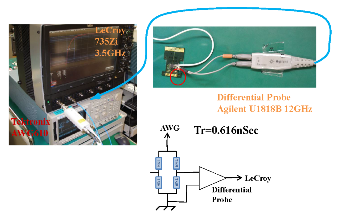
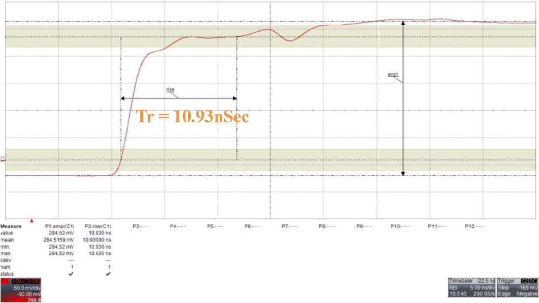
As shown in Fig. 1, a pulse of tr = 0.616 ns 1 VP-P was input to the VCC pin and the response of the sensor output was observed.
Rise time tr =10.93 ns ≥ a bandwidth of 32 MHz is confirmed.
This input-output propagation delay time is due to the time constants of the resistance and parasitic capacitance of the TMR sensor’s internal circuit.
If a two-pole sensing magnet is used, this means that signals in the ultra high-speed range up to 1,920 Mrpm can be handled, and the angle error due to output delay time for most angle detection needs is negligibly small.
Prediction feature to compensate for output delays in TMR sensors with digital signal processing
On the other hand, digital sensor products must consider the output delay caused by the ASIC’s calculation process in addition to analog factors.
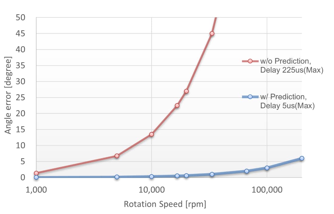
If the output delay time is significant, there is a concern that the angle error may increase. To address this, TDK’s digital TMR sensors are equipped with an output delay prediction feature. This feature enables the output to be projected into the future by the output delay time emulating real-time behavior.
Table 1 and Fig 3 below show the angle error due to output delay time with and without the prediction feature.
| Rotation speed [rpm] |
Rotation period [μS] |
Angle Error [deg] | |
|---|---|---|---|
| w/o Prediction, Delay 225μs(Max) |
w/ Prediction, Delay 5μs(Max) |
||
| 1,000 | 60,000 | 1.4 | 0.0 |
| 5,000 | 12,000 | 6.8 | 0.2 |
| 10,000 | 6,000 | 13.5 | 0.3 |
| 16,667 | 3,600 | 22.5 | 0.5 |
| 20,000 | 3,000 | 27 | 0.6 |
| 33,333 | 1,800 | 45 | 1.0 |
| 66,667 | 900 | 90 | 2.0 |
| 100,000 | 600 | 135 | 3.0 |
Table 1. Angle error due to output delay time
[Formula]
Angle error due to output delay time [deg] = 360 [deg] * delay time / rotation period
Conclusion
TDK’s analog sensor products have a sufficiently high output response speed so that they can be used without any output delay time measures, thus contributing to cost reduction.
TDK digital sensor products can be used without increasing angle error due to output delay time, thanks to their prediction feature.
Relative information
Related products
For questions, requests, sample/evaluation board requirements, etc., please contact us.
Some sensor products are also not listed on the web. For more information, please contact your local sales representative.


