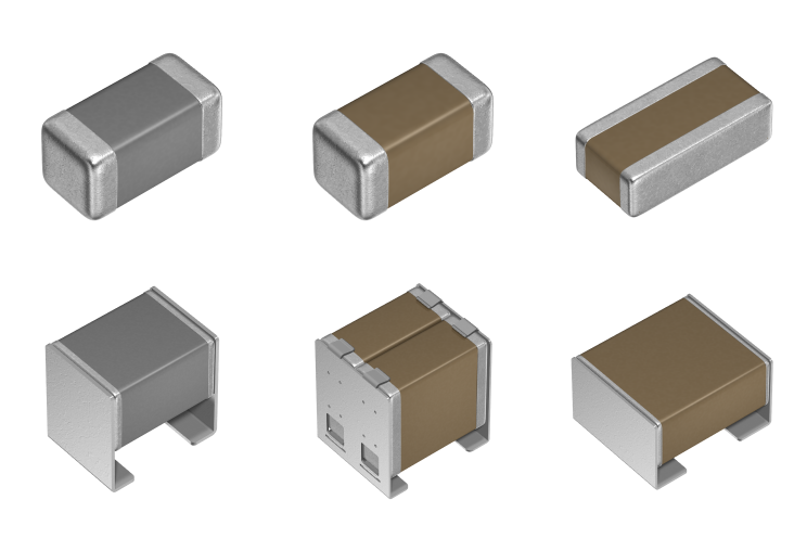
Low-Resistance Metal-Terminal Multi-Array MLCC MegaCap CA Series
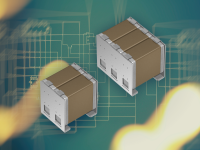
The CA series low-resistance metal-terminal multi-array MLCC Megacap features a structure in which MLCCs are arrayed horizontally in multiple units, combined with optimized metal terminals, meeting the high capacitance, low ESR, and high reliability demands of automotive applications. In addition to automotive-grade products, general-grade products are also available, covering a wide range of applications from automotive equipment to consumer and industrial devices.<br>
This article organizes the key points needed for adoption consideration from the perspectives of CA series structure and application.
 Contact Us
What is the CA Series?
The CA Series is a metal-terminal MegaCap comprised of multiple MLCCs arranged in a multi-array configuration. It meets the automotive requirements for high capacitance, low ESR, and high reliability. By mitigating board flexure and thermal stress, the metal terminals help reduce the risk of cracking in the ceramic bodies and solder joints. Products with C0G characteristics are suitable for resonant circuits in wireless power transfer systems, while products with X7R characteristics are suitable for smoothing circuits in OBCs and DC/DC converters.
CA Series Structure and Features
The CA series is an automotive-grade, low-resistance, multi-array Megacap in which multiple MLCCs are joined with metal terminals.
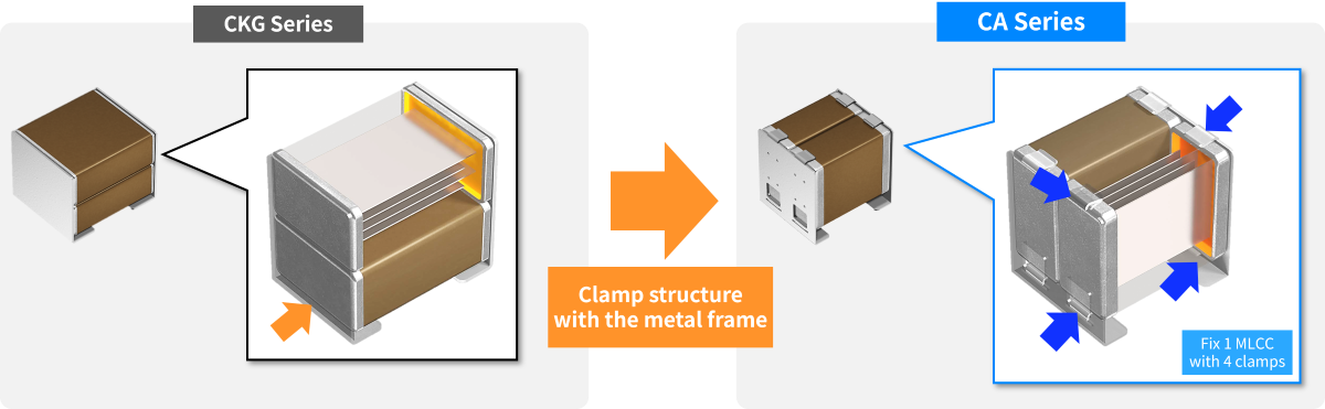
It adopts a structure in which MLCCs are arranged horizontally, achieving higher capacitance through 2 or 3-unit array configurations. In addition, the optimized metal terminal material enables lower resistance. Furthermore, the metal terminals mitigate stress on the MLCC ceramic body caused by board flexure and thermal shock.
| |
|---|---|
| MLCCs and metal frames are joined with high temperature solder | Hybrid joining with solder and clamps reduces the risk of MLCC detachment during high temperature reflow |
Differences from Conventional Product (CKG Series) and Advantages of the CA Series
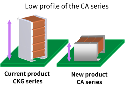
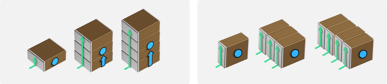
The primary differences between the CA Series and the conventional CKG Series are the orientation in which the MLCCs are arranged and the materials used for the metal terminals. Whereas the conventional series stacks MLCCs vertically, the CA Series uses a side-by-side arrangement. Because adding MLCCs does not significantly increase the product height or raise the center of gravity, the mechanical stress and risks associated with vibration can be more easily reduced. In addition, because the distance between each MLCC and the circuit board can be maintained more consistently, increases in ESR and ESL can be minimized even as the number of MLCCs increases.
This structure enables the CA Series to be offered in configurations of up to three units, supporting higher capacitance. Furthermore, the use of optimized materials for the metal terminals helps reduce resistance.
■Benefits from Difference in MLCC Arrangement Orientations
➡Current ●Center of gravity
| Conventional CKG Series: Vertical Arrangement | CA Series: Horizontal Arrangement | ||
|---|---|---|---|
| |||
| Taller & Higher CG ➡Greater vibration risk. | Increasing capacitance by adding MLCCs vertically is difficult. | Low Profile & Stable CG ➡Lower vibration risk. | Capacitance can be increased by adding MLCCs horizontally. |
| Longer Distance to PCB ➡ESR / ESL increases. | Consistent Distance to PCB ➡ESR / ESL stays low. | ||

| |||
| The CA series can expand capacitance while keeping the profile low | |||
■Impedance Characteristics
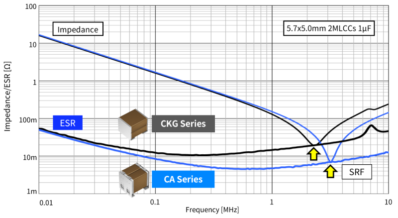
Five Key Features Supporting the Reliability of the CA Series
The CA series contributes to reducing risks anticipated in automotive applications, including cracking of the MLCC ceramic body and solder joints, heat generation during current flow, and chip dropout during reflow.
1. Reducing Risk of MLCC Ceramic Body Cracking Due to Board Flexure
When an MLCC is subject to stress caused by board flexure, cracks may occur in its ceramic body. In the CA Series, the metal terminals help relieve stress caused by board flexure and reduce the load transferred to the MLCC ceramic body. This helps reduce the risk of ceramic body cracking.
2. Reducing Risk of Solder Cracking Due to Temperature Cycling
Repeated temperature changes cause thermal stress in solder joints because of the difference in the coefficients of thermal expansion between the MLCC and the board. In the CA Series, the metal terminals help relieve this thermal stress and reduce the load on the solder joints. This helps reduce the risk of solder cracking caused by temperature cycling and thermal shock.
3. Low Resistance Reduces Heat Generation under High Current Conditions
Low resistance is achieved by optimizing the materials used for the metal terminals. Reducing ESR helps suppress heat generation from current flow. In a representative evaluation, ESR at the resonant frequency was approximately 60% lower than that of the conventional type, and a comparable reduction in heat generation can also be expected.
The reduction rates for ESR and heat generation vary depending on product specifications and evaluation conditions.
4. Hybrid-joint Structure Reduces Risk of MLCC Detachment during Reflow Soldering
In addition to high temperature solder, each MLCC is secured by four clamps. This hybrid-joint structure, which combines solder and clamps, helps reduce the risk of MLCC detachment during high-temperature reflow soldering. It is also compatible with the recommended reflow temperature of 260°C for lead-free solder.
5. Low Profile, Low Center of Gravity, Vibration Resistant with Side-by-Side Multi-Array Structure
The CA Series uses a multi-array structure in which multiple MLCCs are arranged side by side. Even when the number of MLCCs is increased, the product height and center of gravity stay relatively low, reducing stress from vibration. In addition, MLCCs can be added in the horizontal direction, enabling higher capacitance through two- and three-unit configurations.
Application 1: C0G Products for Resonant Circuits in Wireless Power Transfer Systems
In the LC resonant circuit used for wireless power transfer (WPT), capacitors with stable capacitance over changes in temperature and applied voltage are required. The C0G products in the CA Series exhibit minimal capacitance change due to temperature and applied voltage, helping ensure stable operation of the resonant circuits.
As the power levels of wireless power transfer systems for EVs increase, the AC current flowing through the capacitors also increases, making heat generation during operation a challenge. The CA Series achieves low ESR using optimized metal-terminal materials, helping suppress heat generation.
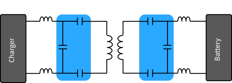
The figure below shows an example configuration of the LC resonant circuit located on the transmit and receive sides of the power transfer circuit. The capacitors shown in blue are the capacitors used for LC resonance.
● Capacitors used for LC resonance
Key Selection Criteria for Capacitors in Wireless Power Transfer LC Resonant Circuits
- Minimal change in capacitance due to temperature and applied voltage
- Rated voltage sufficient to withstand the expected applied voltage
- Low ESR to suppress heat generation caused by high current flow
Application 2: X7 Products for Smoothing Circuits in OBCs and DC/DC Converters
Smoothing circuits require high capacitance to suppress power supply voltage ripples caused by rectification and voltage conversion. OBCs and DC/DC converters handle high voltages and high power levels, so they require capacitors that provide both high capacitance and high voltage ratings.
In addition, ripple current flows through the capacitors in smoothing circuits. When ESR is high, this can result in heat generation. Therefore, low ESR is also important for suppressing heat generation.
The X7R products in the CA Series achieve high capacitance through a multi-array configuration comprising multiple interconnected MLCCs. In addition, optimized metal terminal materials help reduce resistance, contributing to the suppression of heat generation caused by ripple current. Providing product options that include high voltage rated products, the CA Series meets the requirements of smoothing circuits in OBCs and DC/DC converters.
The following figure shows examples of smoothing applications in automotive power circuits, including OBCs and DC/DC converters. The CA Series is well suited for smoothing applications in automotive power circuits that handle high voltages and high power levels, such as OBCs and DC/DC converters.
- ■Automated Driving / ECU for ADAS
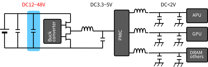
● Input decoupling capacitors :
Higher reliability is required for power circuits
as automotive functions become more advanced
- ■xEV DC-DC Converters
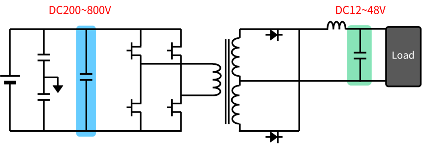
● Input decoupling capacitors :
Higher battery voltages require MLCCs rated for several hundred volts
● Output decoupling capacitors :
High voltage on output lines also calls for higher reliability
Conclusion
The CA Series is a metal terminal MLCC configuration designed to meet the needs of automotive power circuits, including high capacitance, low ESR, mitigation of cracking, and high soldering reliability. It offers products for a variety of applications, including resonant circuits in wireless power transfer systems, smoothing circuits in OBCs, and decoupling circuits for automotive DC/DC converters and inverters.
When selecting a product, first check the capacitance, rated voltage, temperature characteristics, and package dimensions.
- [View the CA Series Product Lineup]
- [Download the CA Series Datasheet for Automotive]
- [Download the CA Series Datasheet for Commercial]
FAQ
Q1. What happens to the MLCC (Multilayer Ceramic Chip Capacitor) once it is cracked?
A1. Click here for details
Q2. Does TDK offer any products providing solutions for flex cracking?
A2. Click here for details
Q3. Does the capacitance of an MLCC change with temperature?
A3. Click here for details
Q4. Why do MLCCs (Multilayer Ceramic Chip Capacitors) generate heat with the ripple current?
A4. Click here for details


Related Links