Q.
Flex Crack Countermeasures (8): Does TDK offer any products providing solutions for flex cracking?
- Capacitors >
- Multilayer Ceramic Chip Capacitors
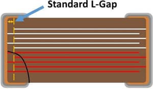
Figure 1: A diagram showing the "L" gap on a standard MLCC.
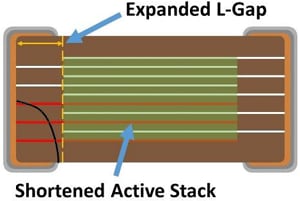
Figure 2: A diagram showing how the expanded "L" gap helps prevent a short circuit from flex cracking.
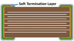
Figure 3: A diagram showing the location of the conductive resin layer (shown in green for emphasis).TDK's Soft Termination MLCC's have a layer of conductive resin built into the termination (Figure 11). This layer of resin, located between the Cu and Ni layers, helps absorb mechanical stresses from bending and vibration to prevent a crack from occurring. When the part undergoes extreme bending, the termination is designed to separate from the resin before a crack develops.
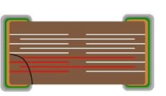
Figure 4: A diagram showing the internal architecture of a serial design capacitor. A short has not occurred, even though the part has cracked.TDK's Serial Design capacitors are effectively two capacitors in series, in a single ceramic body (Figure 12). These caps are designed to satisfy certain specifications for series caps on battery lines.
The two capacitors ensure that if one cracks, there still exists a second capacitor. This helps prevent a short circuit in the event of a crack. However, TDK's serial design is also equipped with Soft Termination. This helps prevent a crack in the first place.
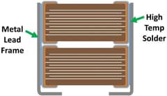
Figure 5: A diagram showing the construction of a TDK MEGACAP.TDK's MEGACAP is an MLCC with a metal lead frame available in single and stacked type (Figure 13). The metal leads absorb much of the stress from bending and vibrations.
A.
TDK has many flex cracking solutions including, Open Mode, Soft Termination, Serial Design, and MEGACAP.
Open Mode caps have an extended "L" gap (the distance between the termination and the electrode) as shown in Figures 1 and 2. This means that when the common 45° crack occurs, it will not travel through the active stack, and therefore will create an open circuit instead of a short circuit.
Figure 1: A diagram showing the "L" gap on a standard MLCC.
Figure 2: A diagram showing how the expanded "L" gap helps prevent a short circuit from flex cracking.
Figure 3: A diagram showing the location of the conductive resin layer (shown in green for emphasis).
Figure 4: A diagram showing the internal architecture of a serial design capacitor. A short has not occurred, even though the part has cracked.
The two capacitors ensure that if one cracks, there still exists a second capacitor. This helps prevent a short circuit in the event of a crack. However, TDK's serial design is also equipped with Soft Termination. This helps prevent a crack in the first place.
Figure 5: A diagram showing the construction of a TDK MEGACAP.
>>Multilayer Ceramic Chip Capacitors Product site
>>Flex Crack Countermeasures in MLCCs Outline
For any other product-related questions or inquiries, please contact us throughone of our sales representatives or this website.

