Product OverviewWhat is the difference between Zener/TVS diodes and varistors? Four comparison aspects to consider with regard to usage
Chip varistors and TVS diodes are commonly used as over-voltage protection components.Their structural design and manufacturing methods are completely different, but they offer similar characteristics with regard to protection from static electricity.
They generally can therefore be used interchangeably in a circuit, but there are cases where chip varistors are considered to be not suitable.
For historical reasons, many of the specification items given in catalogs and data sheets are different, which makes it difficult to compare characteristics based solely on these data, unlike in the case of capacitors and other general components.
The aim of this article is to clarify the difference between varistors and diodes and to introduce data that can be used to compare the two.
Contents
- History
- Differences between chip varistors and TVS diodes
- Four key aspects for use of chip varistors and TVS diodes in controller area networks (CAN)
- Features of TDK chip varistors — ESD durability against repeated ESD stresses
- Features of TDK chip varistors — Miniaturized dimensions
- Publication of data sheets on the web
- Contact
History
Zinc oxide varistors developed in 1968 were adopted to protect diodes from lightning. Diodes on the other hand were used mainly for rectification, so their application area was different. This is the reason why many items listed in catalogs and data sheets are different, making a direct comparison difficult. The applicable Automotive Electronics Council standards also differ substantially, with AEC-Q101 being used for TVS diodes and AEC-Q200 for varistors.
Differences between chip varistors and TVS diodes
Structure
Chip varistors are ceramic semiconductor products based mainly on zinc oxide. As the illustration below shows, chip varistors have a laminated structure, with breakdown voltage and capacitance being controlled by the number of layers and the interlayer design. TVS diodes on the other hand are a combination of P-type and N-type semiconductors. They are silicon-based ESD protection components. Some diodes also use Au wire etc.
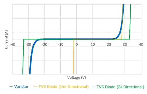
I-V curve
The resistance value of both chip varistors and TVS diodes changes greatly depending on the applied voltage. Chip varistors enable bi-directional electrostatic protection. TVS diodes used to be almost exclusively uni-directional, but there are now an increasing number of bi-directional TVS diodes as well. It is important to note, however, that there are cases where the behavior differs depending on the direction.
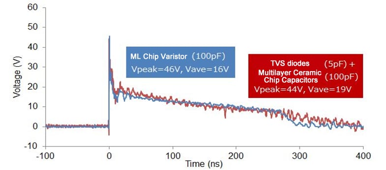
Reaction speed to over-voltage
Based on recollections of disc varistors and similar in the early days of varistors, one often hears that varistor response is slow. But as the graph below shows, the response speed to over-voltage is similar for chip varistors and TVS diodes. When a +8kV HBM voltage according to IEC 61000-4-2 is applied, the peak is reached within 1 ns, and the voltage at the protected component has dropped to about zero after 400 ns.
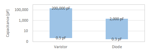
Capacitance
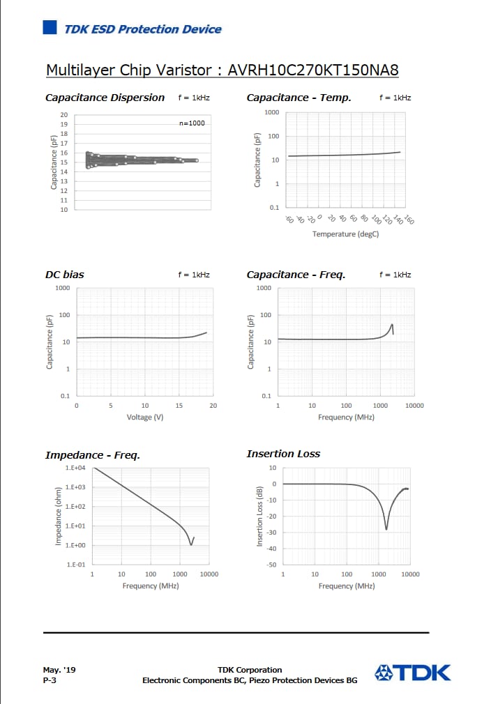
The capacitance range of varistors and TVS diodes differs considerably. Because chip varistors have a multilayer structure, capacitance can be increased by increasing the number of internal electrode layers. When comparing sizes of EIA 0805 and under, the difference in the highest capacitance is close to a factor of 100, as shown below. In some lines requiring a parallel MLCC configuration, it may therefore be possible to use a single chip varistor.
Other characteristics
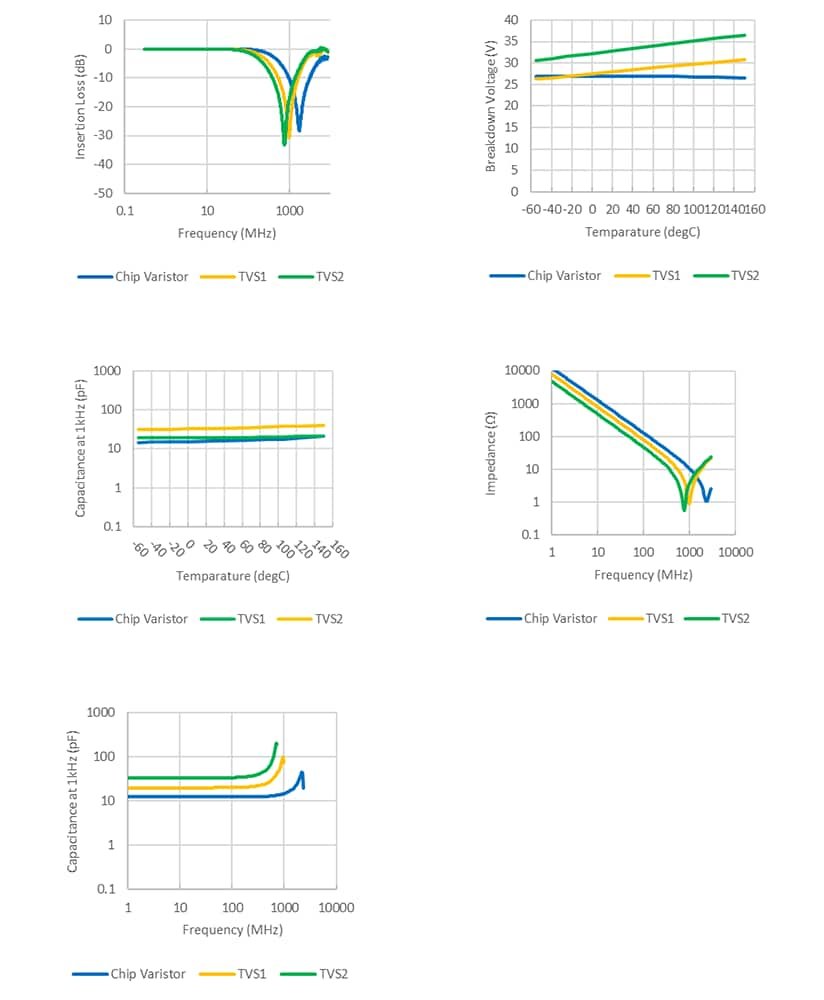
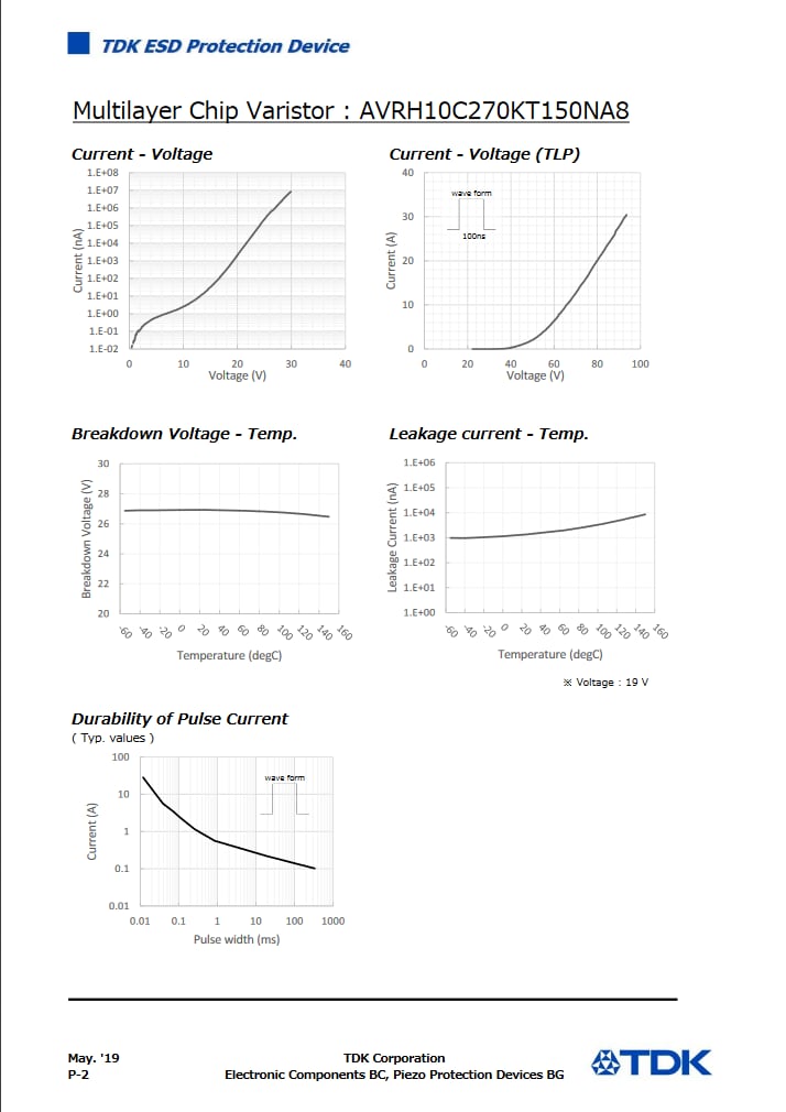
With regard to miscellaneous other characteristics such as thermal characteristics and insertion loss, there are slight differences between chip varistors and TVS diodes, but a comparison at the same specifications will show similar behavior. Because data sheets will show the respective curve, a comparison with TVS diodes is possible.
Related Links
Selection Guides
Four key aspects for use of chip varistors and TVS diodes in controller area networks (CAN)
In a controller area network (CAN), antistatic components are used to protect the CAN transceiver. Some points to consider with regard to selecting components for use on CAN lines are described below.
Maximum allowable circuit voltage
In a CAN with serial bus topology, the CANH and CANL signals are used to specify the dominant and recessive level state.
When dominant, the CANH line is at about 3.5 V. The electrostatic protection component must function as an insulator at this voltage.
Therefore a component with a maximum allowable circuit voltage of 3.5 V or higher must be selected in this case.
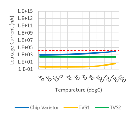
Because the leak current of the electrostatic protection component is temperature dependent,
the ambient temperature in the actual usage environment must also be taken into consideration.
The graph below shows the thermal characteristics of leak current in a representative chip varistor and TVS diode.
The leak current increases towards higher temperatures, but it is designed to not exceed 50 µA.
Capacitance
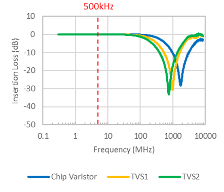
The maximum transfer rate in a CAN will be 1 Mbps. Electrostatic protection components inserted in parallel with the circuit should not obstruct communication at this speed. Therefore components with low insertion loss at 1 Mbps (= 0.5 MHz) must be selected. The graph below shows the insertion loss for a chip varistor and two TVS diodes. It can be seen that any of these can be inserted without obstructing CAN communication.
Surge protection capability
Electrostatic protection components serve to prevent damage to ICs and peripheral components used in a set. As an example, the ESD durability ratings for an automotive CAN transceiver are shown below.
| Tranceiver | Vender | Transfer rate | Vesd HBM CANH, L | SPLIT | Other |
|---|---|---|---|---|---|
| A | Company A | 1Mbps | ±12kV | ±12kV | ±12kV |
| B | Company B | 1Mbps | ±12kV | ±10kV | ±4kV |
| C | Company C | 1Mbps | ±6kV | ±6kV | ±4kV |
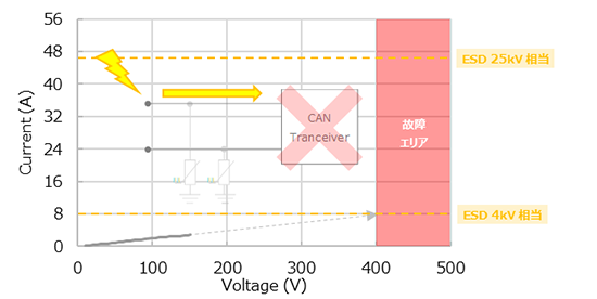
From the table, it can be seen that the CAN transceiver may be destroyed if a voltage of 4 kV or higher is applied.
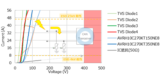
If no electrostatic protection component is used, an 8 A current will flow in the CAN transceiver in case of a 4 kV electrostatic discharge, thereby destroying it. As can be seen from the illustration below, the resistance value of the varistor or TVS diode rapidly drops to below 2 ohms when over-voltage is applied.
Because the major part of the current generated by the ESD flows to the electrostatic protection component, the CAN transceiver is protected. Using TLP data, it is possible to perform simulations at the design stage to verify the current that will reach the CAN transceiver. This is only a simple example, but by knowing the characteristics of other electronic components as well, it is possible to check ESD durability before actual testing.
ESD durability
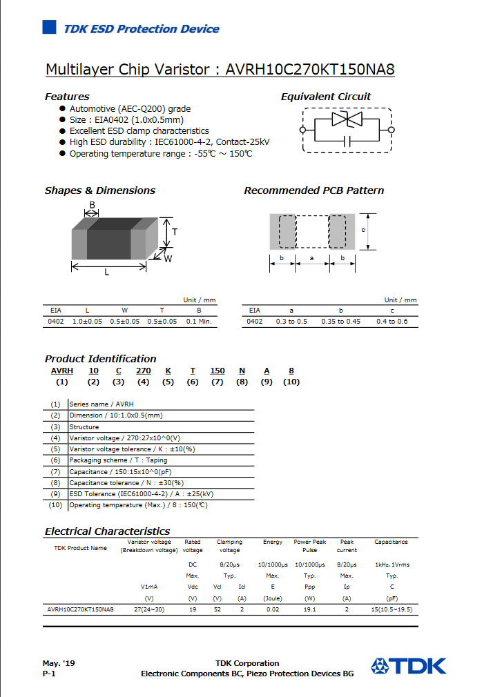
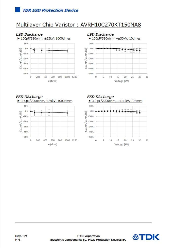
In many cases, one needs to determine the ESD durability as a set, and the same performance is required of the electrostatic protection components. The ESD durability for a product can be checked in the data sheet.
Related Links
Application Note
Features of TDK chip varistors — ESD durability against repeated ESD stresses
The resistance of a varistor against repeated surges depends significantly on material design choices, such as the type and composition of additives to the main material zinc oxide (ZnO). Chip varistors from TDK benefit from proprietary materials developed by harnessing the materials technology of the company. As a result, the varistors feature excellent durability against repeated surges. TDK also offers products that can substitute Zener diodes in applications involving frequent on/off switching such as for solenoid valves and stepping motors. For details, see the article " Chip Varistors That Excel in Resisting Repeated Surges"
Related Links
Application Note
Features of TDK chip varistors — Miniaturized dimensions
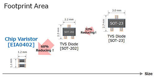
TDK has realized miniaturized varistors with a form factor of EIA 01005 (0.4 x 0.2 mm). The company also mass-produces the industry's smallest AEC-Q200 compliant EIA 0402 (1.0 x 0.5 mm) size for automotive applications.
Related Links
Selection Guides
Publication of data sheets on the web
The various data mentioned above are from data sheets that TDK is making available on the Internet. This provides all the data that are required to easily perform comparisons with TVS diodes.
Contact Information
Related Links
Product Map
Product Portal
- Chip Varistors / Ceramic Transient Voltage Suppressors product Information
- A comprehensive guide to information on Chip Varistors / Ceramic Transient Voltage Suppressors from the TDK Group.
- Ceradiode product Information
- A comprehensive guide to information on Ceradiode from the TDK Group.
- Multilayer Chip Protectors product Information
- A comprehensive guide to information on Multilayer Chip Protectors from the TDK Group.
- Voltage Protection Devices product Information
- A comprehensive guide to information on Voltage Protection Devices from the TDK Group.


