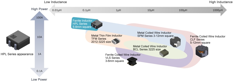
Power Inductor - HPL Series

It is characterized by its ability to handle large currents with high efficiency, making it ideal for circuits requiring large currents, such as ADAS image processing circuits. Additionally, due to its unique structure with no connection points, it ensures high reliability with reduced risk of open defects.
In this article, we will explain the structure, features, and applications of the HPL Series in an easy-to-understand manner that is useful for everyone.
Table of Contents
Product Overview
The following is an overview of the HPL Series.
| Series | HPL Series |
|---|---|
| Product Overview |
・High current, low inductance ferrite inductor for automotive application. |
| Features | ・High current capability ・Low resistance ・High reliability ・Low leakage flux ・Operating temperature range: -55°C to 155°C (including self-temperature rise) ・AEC-Q200 compliant |
| Applications |
Automotive applications (ADAS ECU, image processors, ultra-high current applications)
|
Product Overview
The following chart shows the structure of the HPL Series. The HPL Series inductor structure is based on a coil frame whcih is contained between two ferrite core plates.
By controlling the distance of the gap between the two ferrite core plates, it is possible to make fine adjustments to the inductance without changing the resistance value.
Product Features
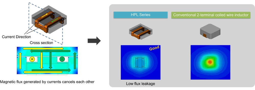
The HPL Series uses high-permeability ferrite materials and utilizes a structure that cancels magnetic flux, contributing to noise reduction with less leakage flux compared to conventional
inductors.Figure 3 shows a comparison of the structure and leakage flux.
Reducing EMI using a structure that cancels magnetic flux
By using low AC-loss ferrite materials and a low-resistance coil frame, the HPL Series achieves higher efficiency in power supply circuits compared to conventional
inductors.Figure 4 shows a comparison graph of AC loss and power supply efficiency.
AC Loss Comparison

Power Efficiency Comparison

Applications
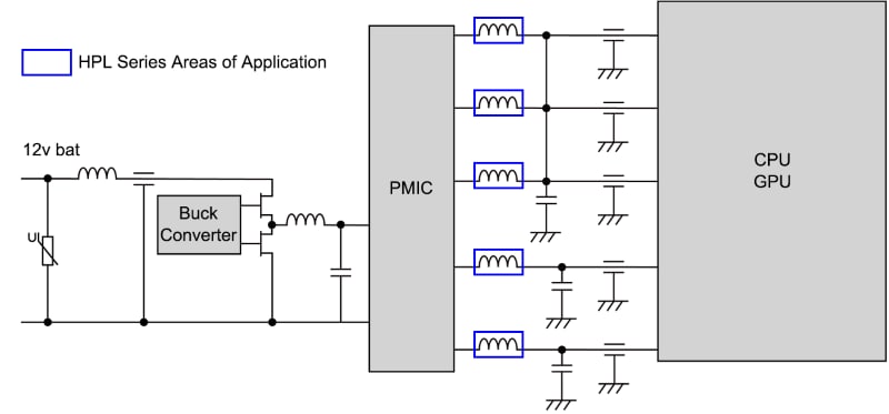
Figure 5 shows an application of the HPL Series as enclosed in the blue boxes. Due to its low inductance and high current capability, the HPL Series is ideal for high-power ECUs, such as image processing circuits for ADAS, which handle high-speed, high-capacity camera images.
ADAS / AD ECU
Product Details
Click on the links below to view detailed information on the HPL series or to purchase samples. We will continue to expand our lineup and meet a wide variety of customer inductor needs.
 Automotive Grade
| Series Type | Application | L x W Dimensions | Height | Inductance | DC Resistance (Max) | Rated Current | Part Number List |
|---|---|---|---|---|---|---|---|
|
|
5.0x5.0mm | 2.8mm | 60~150nH | 0.88mΩ | 19~45.5A | ||
| 3.2mm | 60~80nH | 0.77mΩ | 43~63A | ||||
| 7.5x8.0mm | 4.0mm | 220~330nH | 0.61mΩ | 25~40A | |||
| 8.0x12.0mm | 6.0mm | 220~330nH | 0.55mΩ | 49~78A |
What are power inductors?
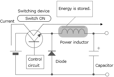
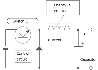
Power inductors are inductors used for power supply circuit such as DC-DC converters. They are also called power coils or power choke coil. One of the inductors' characteristics is that they store energy by self-induction function. Chopper type DC-DC converters use inductors having such characteristics with switching devices for voltage conversion (see Figure 7).
Depending on the processing method, inductors can be classified into multilayer type, thin-film type, and wire-wound type. Since wire-wound type permits large current to flow, most of the power inductors are wire-wound type. Various wound-type power inductor products with ferrite or soft magnetic metal core are offered. Recently, the multilayer type and thin-film type, with which reduction of size and thickness can be achieved, are being improved to allow for larger current.
The voltage is dropped to a desired level in accordance with the duty ratio (the ratio that indicates how long the switch is ON during the switching cycle) setting.
Switching
repeated
Contact Information
Related Links
Product Portal
Selection Guide
Products & Technologies
-
- Product Overview
- Ferrite Shield-Type Automotive Power Inductors
-
- Product Overview
- Power Inductor SPM Series
-
- Product Overview
- Power Inductor TFM Series
-
- Product Overview
- Power Inductor VLS Series
-
- Product Overview
- High frequency power inductors for automotive applications designed for outstanding reliability to reduce failure risks.

