- Capacitors >
- Multilayer Ceramic Chip Capacitors
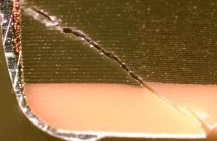
A. The signature flex crack is sometimes referred to as a "45°crack". These cracks originate near the start of the termination (the origin of stress on the part) on the mounted side of the MLCC and continue upwards at a 45° angle (the direction of bending stress on the part) until it reaches the termination at the outer edge of the MLCC (Figure 1).
Figure 1: Stress origin and direction on an MLCC during a convex bend
The 45°crack is the most commonly seen flex crack, but other flex cracks are possible, particularly if the part underwent especially severe bending.
Sometimes a discoloration of the dielectric is visible on the surface, although external visual detection of a flex crack is rare. This area will appear lighter in color than the normal dielectric.
Usually, the crack is only found once the part has undergone a DPA (Destructive Physical Analysis), also called a cross-sectioning (Figure 4).
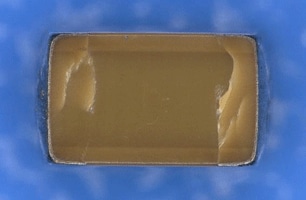
Sometimes, if the MLCC’s termination is removed, the flex crack can be observed, if the crack has propagated the surface (Figure 5).
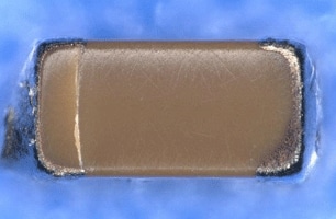
These cracks can sometimes be visible on the bottom of the MLCC (Figure 6).
During cases of severe board stress, cracks could form on both ends of the MLCC.
Figure 2: A cross section of an MLCC that cracked due to excess board flexure
Figure 3: Bottom of an MLCC, showing the origin of a flex crack.
Figure 4: Bottom of an MLCC with the termination removed. Cracks are visible at both ends.
>>Multilayer Ceramic Chip Capacitors Product site
>>Flex Crack Countermeasures in MLCCs Outline
For any other product-related questions or inquiries, please contact us throughone of our sales representatives or this website.


