Deterioration of Mode Conversion Characteristics and EMI Properties Due to Incorrect Selection of ESD (Electrostatic Discharge) Protective Components

Contents
- Introduction: ESD (Electrostatic Discharge) Countermeasures and Their Impact on EMC Performance
- Case Studies
- Verification of Mode Conversion Characteristics (SSD12)
- Verification by Conducted Emission Tests - Conclusion: Importance of Selecting the Right ESD (Electrostatic Discharge) Protective Components (Chip Varistors)
- Contact Us
Introduction: ESD (Electrostatic Discharge) Countermeasures and Their Impact on EMC Performance
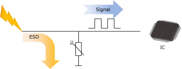
Protective measures are essential for ESD (Electrostatic Discharge) to prevent malfunctions or failures in electronic devices. Typically, ESD protection involves the use of components such as varistors, which are placed between the line of the IC (or similar target for protection) and GND, as shown in Figure 1. ESD protective components are designed to reduce their resistance significantly upon the application of high voltage, such as ESD, effectively channeling the ESD to the GND to protect ICs or similar elements. However because these components are mounted directly on the line, selecting inappropriate ESD protective components can affect the signal on the line even under normal conditions. Examples include high-speed communication lines with differential signals, such as those used in automotive communications' CAN (Controller Area Network) and Ethernet. These can exhibit significant impacts, not only deteriorating communication quality but also potentially affecting EMC (Electromagnetic Compatibility) performance in the worst cases.
Case Studies
As mentioned in the previous section, failure to use appropriate electrostatic discharge (ESD) protection components can lead to degradation of signal quality and deterioration of Electromagnetic Compatibility (EMC) performance. Particularly in differential signal lines, as shown in Figure 2, ESD protection components must be used on both the High and Low sides. During this process, differences in the capacitance of ESD protection components used on each line can degrade the symmetry of impedance across the lines and worsen the mode conversion characteristics. Furthermore, the deterioration of mode conversion characteristics may also degrade EMC performance.
Below we present actual evaluation data to introduce the impact of ESD protection components on Mixed-mode S-parameter and the Conducted Emission test (150Ω method) in CAN communication.
(C1: Capacitance of the ESD protection element on the + side, C2: Capacitance of the ESD protection element on the - side)
• Mode Conversion Characteristics (Ssd12)
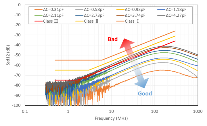
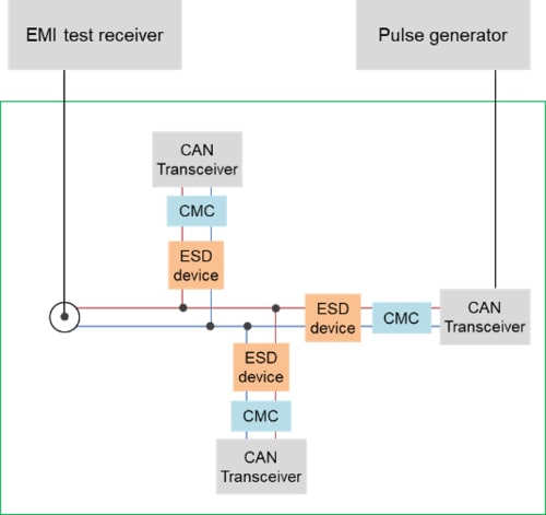
Figure 3 shows the evaluation results of the mode conversion (mode change) characteristics (Ssd12) measurement. This evaluation of mode conversion characteristics is not conducted with the usual 4-port measurement but with a 3-port evaluation as depicted in Figure 4. Despite being a 3-port evaluation, it allows for the assessment of mode conversion characteristics similar to a 4-port evaluation. The vertical axis represents the mode conversion characteristics (Ssd12), and the horizontal axis represents frequency. The plotted data represents the differences in capacitance between lines of the ESD protection components. The higher the Ssd12 value, the worse the characteristic, meaning that noise (common mode) is converted to communication signal components (differential mode), or vice versa (see Appendix for details).
The graph shows that as the difference in capacitance (ΔC) between the lines of the ESD protection components increases, Ssd12 deteriorates.
For reference, the limit line for Ssd12 as per the IEC62228-3 standard for CAN-oriented Common Mode Choke Coils (CMC) is also indicated. When ΔC exceeds 2.7pF, it fails to meet the Class I standard line.
Thus, it's evident that an increase in ΔC leads to actual deterioration in mode conversion characteristics.
• Conducted EMI Test (150Ω Method)
Next, we present results from the Conducted Emission test (150Ω method) as an example of EMC performance deterioration when mode conversion characteristics worsen due to ESD protection components.
The Conducted Emission test measures the conducted noise on the signal line directly using an EMI test receiver. This measurement was conducted using a test board designed for CAN, with an evaluation circuit as shown in Figure 5 (Conducted Emission Test Evaluation Circuit).
For ESD protection, we evaluated both a general CAN-oriented varistor and TDK’s CAN-oriented 2-in-1 Array Varistor (AVRH16A2C270KT200NA8). This AVRH16A2C270KT200NA8 is a 2-in-1 package combining two single-line varistors, capable of protecting one pair of differential signal lines. One advantage of the 2-in-1 type is its ability to minimize the difference in capacitance between lines which leads to better mode conversion characteristics compared to single-line varistors.
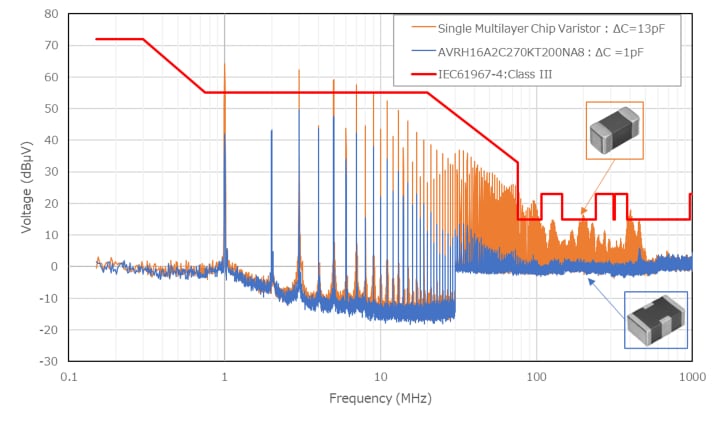
The evaluation results are shown in Figure 6.
The vertical axis represents noise level, and the horizontal axis represents frequency. The orange data represents the worst-case scenario for single varistors with a line-to-line capacitance difference of 13pF (ΔC = 13pF), while the blue data represents the worst-case scenario for AVRH16A2C270KT200NA8 with a line-to-line capacitance difference of 1pF (ΔC = 1pF). For reference, the standard line for class III in IEC61967-4 is also indicated.The single varistor exceeds the standard line from low to high frequencies, whereas the array type varistor remains within the standard line. Overall, the array type varistor also tends to have a lower noise level.
Thus, if the mode conversion characteristics are poor, there is a possibility that the EMC characteristics may worsen even in a steady state where the varistor is not active.
Conclusion: Importance of Selecting the Right ESD (Electrostatic Discharge) Protective Components (Chip Varistors)
This article has introduced how ESD protective components can worsen mode conversion characteristics and, as shown in EMC tests, lead to poor results.
ESD protective components, while designed to prevent electrostatic discharge, can negatively impact EMC performance if incorrectly selected. Mode conversion characteristics are particularly critical in modern automotive communication lines, requiring ESD protective components with favorable mode conversion characteristics.
TDK's varistors for automotive communication are designed with consideration for both ESD and mode conversion characteristics and can be utilized without further reducing EMC performance compared to standard varistors.
For any inquiries about ESD protective components, please contact us.
Click on the Part No. to view detailed information.
| Part No. | Product Shape | Lx W Size | Varistor Voltage 1mA |
Capacitance 1kHz |
Chl-Ch2 Capacitance Difference |
ESD Tolerance 150pF, 330Ω contact |
|---|---|---|---|---|---|---|
| AVRH16A2C270KT200NA8 | 2 in 1 array | 1.6mm × 0.8mm EIA0603 |
27 V | 20 pF typ. | 1 pF max. | 25 kV |
| Part No. | Product Shape | LxW Size | Varistor Voltage 1mA |
Capacitance 1kHz |
Capacitance Tolerance | ESD Tolerance 150pF, 330Ω contact |
|---|---|---|---|---|---|---|
| AVRH10C101KT4R7YA8 | Single | 1.0mm x 0.5mm EIA0402 |
115 V | 4.7 pF typ. | ±0.57. | 25 kV |
| AVRH10C101KT1R2YE8 | Single | 1.0mm x 0.5mm EIA0402 |
110 V | 1.23 pF typ. | ±0.13. | 8 kV |
| AVRH10C221KT1R5YA8 | Single | 1.0mm x 0.5mm EIA0402 |
220 V | 1.5 pF typ. | ±0.13. | 25 kV |
What Are Mode Conversion Characteristics?
Differential communication signals flow in a mode known as differential mode, while noise flows in a mode known as common mode. Occasionally, due to the impact of electronic components used in differential communication lines, this conduction mode may convert from differential mode to common mode or vice versa. This conversion of conduction mode is referred to as mode conversion. Mode conversion can result in differential signals being converted into noise or noise being converted into differential signals, subsequently worsening the ECU's noise tolerance. This can lead to malfunctions of the ECU or the ECU itself may emit noise. These effects are generally attributed to asymmetries in the differential signal line, which are differences in characteristics such as inductance or capacitance.
Related Links
Selection Guide
Application Note
-

- Chip Varistors Prevent Damage of Electronics from Electrostatic Discharge
-

- PCB Layout for ESD Countermeasures | ESD Visualization
-

- How to Use ESD/surge Protection Devices: SMD Varistors
-

- PCB Pattern Design for ESD Countermeasures | ESD Visualization
-

- Example of ESD Countermeasures on Actual Equipment | LED Protection with Chip Varistors


