How to Choose the Right Wire-Bondable NTC Thermistor for Temperature Monitoring in SiC Power Modules

TDK offers a broad lineup, including the NTCWS series.

 Contact Us
What is a Position NTC thermistor?
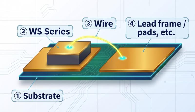
A bondable NTC thermistor is a compact negative temperature coefficient thermistor (NTC thermistor) with gold (Au) electrodes formed on both surfaces—or on the top surface only—enabling direct mounting onto power module substrates via the wire bonding process.
Conventional SMD (surface-mount) and MELF-type NTC thermistors are designed to be mounted on PCB pads. In contrast, bondable NTC thermistors establish electrical connections through wire bonding, significantly reducing dependence on board trace patterns.

Key Characteristics of NTC Thermistors
An NTC thermistor (Negative Temperature Coefficient Thermistor) is a resistive element whose resistance decreases as temperature rises. This property enables real-time detection of temperature changes as voltage signals in a circuit, supporting applications such as cooling control, operation limiting, and overheat protection.
Key parameters:
- R25 (Nominal Resistance):Resistance at 25°C (e.g., 10 kΩ)
- B Constant (B25/85):An index indicating temperature sensitivity. A higher B constant means greater sensitivity to temperature changes.
- Tolerance:Resistance accuracy (±1% or ±3%)
In TDK's NTCWS series, for example, the NTCWS3UF103FC1GT90B offers R25 = 10 kΩ ±1% and B25/85 = 3930 K ±1%.
What Is Wire Bonding?
Wire bonding is a mounting technology that connects semiconductor chips to external electrodes using thin metal wires (aluminum, gold, copper, etc.). It is widely adopted in power module manufacturing. Mounting the NTC thermistor simultaneously within this process enables integrated temperature-sensing design without requiring additional assembly steps.
Applications in Automotive Power Modules
The primary application of bondable NTC thermistors is temperature sensing of SiC/IGBT chips inside power modules mounted in automotive inverters. When SiC devices generate heat within a power module, the NTC thermistor placed nearby detects the temperature change and functions as a trigger for cooling system control or operation limiting.
Key applications:
- Automotive inverters (motor drive for EV/HEV)
- DC-DC converters
- On-board chargers (OBC)
- Industrial power modules (inverters, UPS, solar PCS)
Why Do Power Modules Need Dedicated Wire-Bondable NTC Thermistors?
Challenges of Conventional Methods (MELF/SMD Chip NTCs)
The conventional methods used for temperature sensing in power modules mainly include the following:
| Typr | Features | Challenges |
|---|---|---|
| MELF-type NTC | High heat resistance and high reliability | Relatively expensive; requires mounting on a substrate pattern |
| Chip NTC (SMD) | Low cost and highly suitable for mass production | Measures only the ambient temperature; difficult to place close to the heat-generating component |
| Wire-bondable NTC | Can be placed close to the heat-generating component | Generally relatively expensive; careful selection of the electrode design is important |
The Fundamental Constraint of High-Voltage Environments
Voltages ranging from several hundred volts to several kilovolts are applied to the mounting lands of power semiconductors inside power modules. Conventional NTC thermistors, including SMD and MELF types, do not have sufficient insulation performance to withstand these voltages. As a result, they can only be placed at locations away from the semiconductor chip.
This leads to the following chain of challenges:
❌Measuring at a location away from the heat-generating component → Delays and errors in temperature detection
❌Applying operating limits at temperatures lower than the actual heat-resistance rating to compensate for low detection accuracy → Power semiconductor performance is constrained
❌Increasing the number of power semiconductors to achieve equivalent output under these performance constraints → Increased cost and mounting area
What Wire-Bondable NTC Thermistors Can Solve
Wire-bondable NTC thermistors enable placement adjacent to the die of a power semiconductor without depending on substrate patterns.
The main benefits include:
✅High-accuracy temperature detection immediately adjacent to SiC/IGBT chips
✅Minimizing the distance from the heat-generating component and enabling safe operation control near the upper temperature limit
✅Greater layout freedom without restrictions from substrate patterns
✅Improved temperature-detection accuracy, allowing the performance of power semiconductors to be fully utilized
Technical Requirements for Temperature Sensing in SiC Power Modules
SiC devices can operate at higher junction temperatures than conventional silicon (Si) devices. At the same time, accurate temperature measurement near heat-generating components is essential to fully realize their high efficiency.
Heat Generation Characteristics of SiC Devices and Temperature Limits
SiC power devices offer high heat resistance. However, switching losses and conduction losses inside power modules can create localized high-temperature conditions. For automotive inverters, the design upper limit for junction temperature (Tj) is generally set at approximately 175–200°C.
By contrast, conventional silicon-based power modules typically operate at around 125–150°C. As the industry shifts to SiC, the performance requirements for temperature-sensing components are also becoming more demanding.
Five Key Specifications Required for Automotive NTC Thermistors
The following checklist summarizes the technical requirements that designers should confirm when developing automotive power modules equipped with SiC devices.
| Item | Specification | Requirement / Consideration |
|---|---|---|
| ① Maximum operating temperature | 175–200°C | To withstand the high-temperature operating environment of SiC devices |
| ② Chip size | Compact devices approximately 0.3–0.5 mm square | Because mounting space inside power modules is extremely limited |
| ③ Electrode structure | Compatible with a two-electrode configuration on the top surface, including Au electrodes | To enable wire-bonded mounting close to the heat-generating component |
| ④ Assembly-process compatibility | Soldering / silver sintering (compatible with low-oxygen atmospheres) / wire bonding | Selection must match the power-module manufacturing process |
| ⑤ Automotive reliability standard | AEC-Q200 compliant | To ensure the reliability of automotive electronic components |
Electrode Material Requirements for Each Assembly Process
Because power module manufacturing involves multiple assembly processes, it is important to confirm the compatibility of the NTC thermistor’s electrode materials with the selected process.
| Assembly process | Compatible electrode material | Main points to note |
|---|---|---|
| Wire bonding (Al wire) | Top side: Ni-Au electrodes | Confirm the maximum Al wire diameter, such as 150 μm. |
| Wire bonding (Au/Cu wire) | Top side: Ni-Au electrodes | Some products support wire diameters of up to 300 μm. |
| Solder mounting | Bottom side: Ag/Ni-Au electrodes | Confirm lead-free compatibility. |
| ilver sintering (low-oxygen atmosphere) | Bottom side: Ag thick-film electrodes | Confirm whether silver corrosion resistance is required. |
How to Choose a Wire-Bondable NTC Thermistor and What Are the Key Evaluation Criteria?
The four key criteria for selecting a wire-bondable NTC thermistor are: ① maximum operating temperature, ② chip size, ③ electrode structure, and ④ assembly-process compatibility.
① Selecting the Maximum Operating Temperature
- Inverters equipped with SiC devices: Products rated for 175–200°C are recommended.
- Power modules equipped with Si-IGBTs: Products rated for 125–155°C are often sufficient.
- As a general rule, select a product with sufficient temperature margin, or derating, relative to the maximum temperature of the operating environment.
TDK’s lineup covers multiple temperature ranges from 125°C to 200°C.
② Selecting the Chip Size
Because mounting space inside a power module is extremely limited, chip size is an important design trade-off.
- When small size is the priority (severe space constraints): Approximately 0.3–0.35 mm square
- General-purpose applications: Approximately 0.4–0.5 mm square
- Specific applications (such as replacing MELF types): 1.6 mm square or larger
A representative product in TDK’s NTCWS series, NTCWS3UF103FC1GT90B, is a compact device measuring L × W = 0.33 ± 0.04 mm, with a thickness of 0.25 mm or less.
③ Confirming the Electrode Structure
| Electrode specification | Features | Suitable applications |
|---|---|---|
| Top-and-bottom electrodes (conventional type) | Highly versatile; mounted on a substrate pattern | SMD mounting and replacement of MELF types |
| Two electrodes on the top surface (dedicated wire-bondable type) | No substrate pattern required; high placement flexibility | Placement close to heat-generating components inside power modules |
④ Confirming Assembly-Process Compatibility
Check the manufacturing process used for the power module being designed—such as soldering, sintering, or wire bonding—and confirm that the NTC thermistor’s electrode specifications are compatible with the selected process.
If you have requirements for temperature-sensing design in power modules, please request samples of TDK’s wire-bondable NTC thermistors. We can also recommend suitable products, including identifying devices that meet your requirements.
High Reliability of the TDK NTCWS Series: Reliability Test Data for Automotive Environments
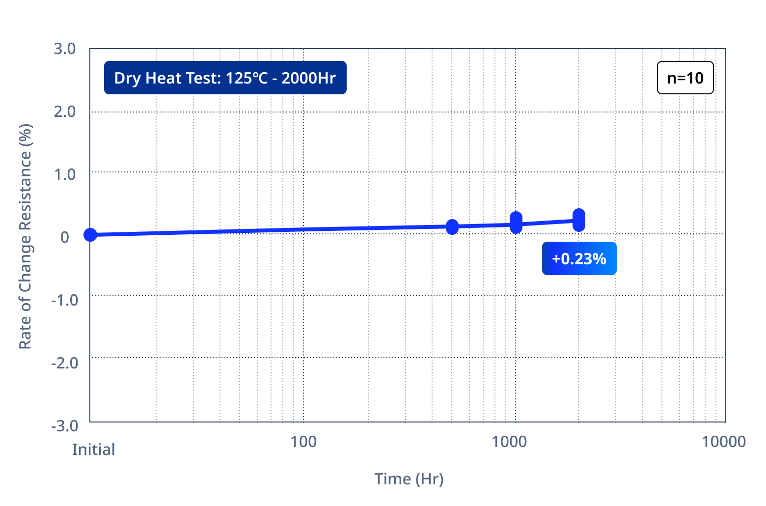
The NTCWS series delivers high reliability under a wide range of environmental conditions. For example, in the Dry Heat Test, the products are exposed to an environment of 125°C for 2,000 hours. Despite this severe test condition, the resistance change after 2,000 hours is only +0.23%, demonstrating stable performance.
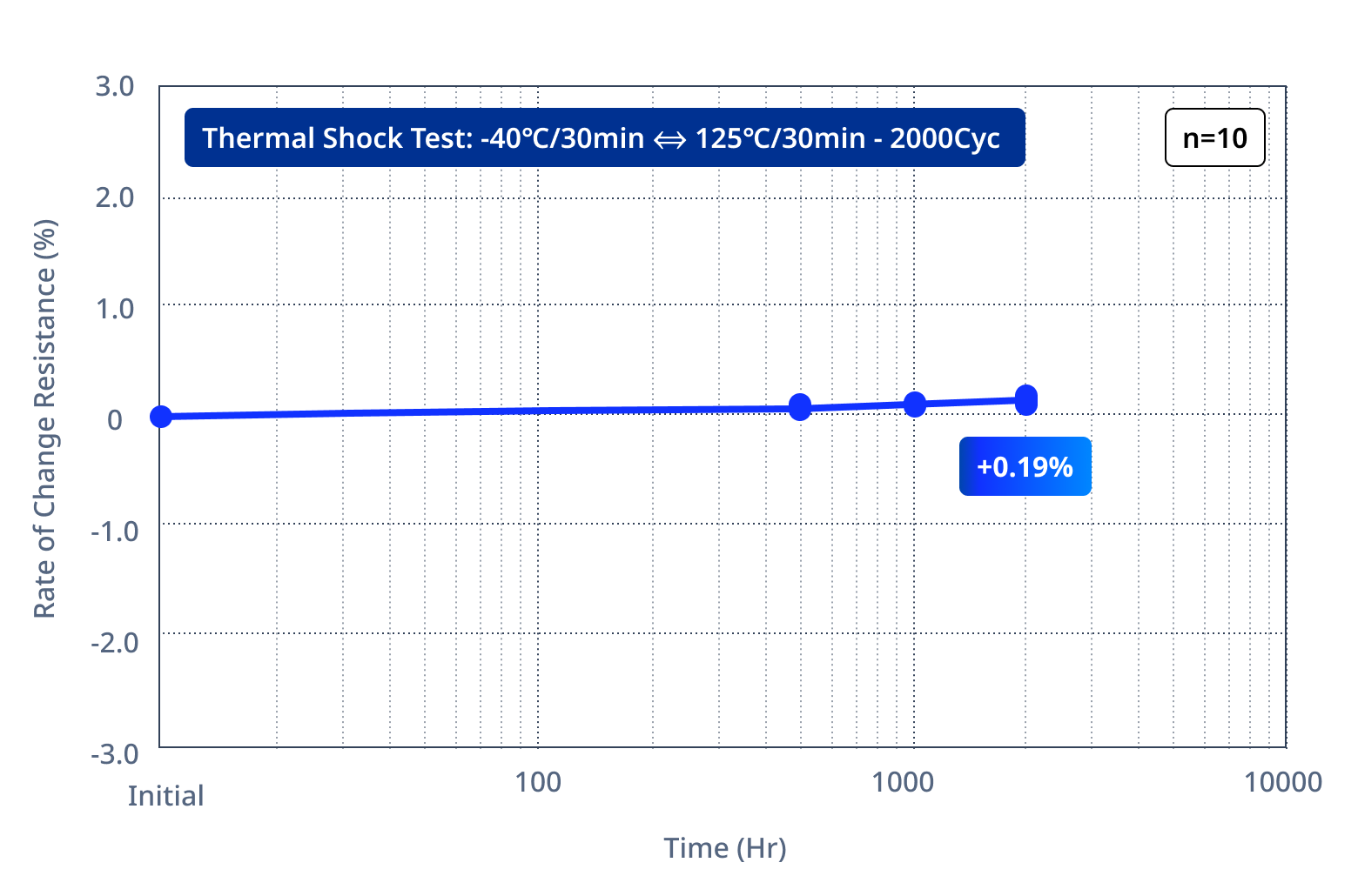
In the Thermal Shock Test, the products are exposed to low and high temperatures of −40°C and 125°C, respectively, for 30 minutes each. Although this is an extremely demanding test condition because the products are subjected to rapid temperature changes, the resistance change after 2,000 cycles remains stable at +0.19%.
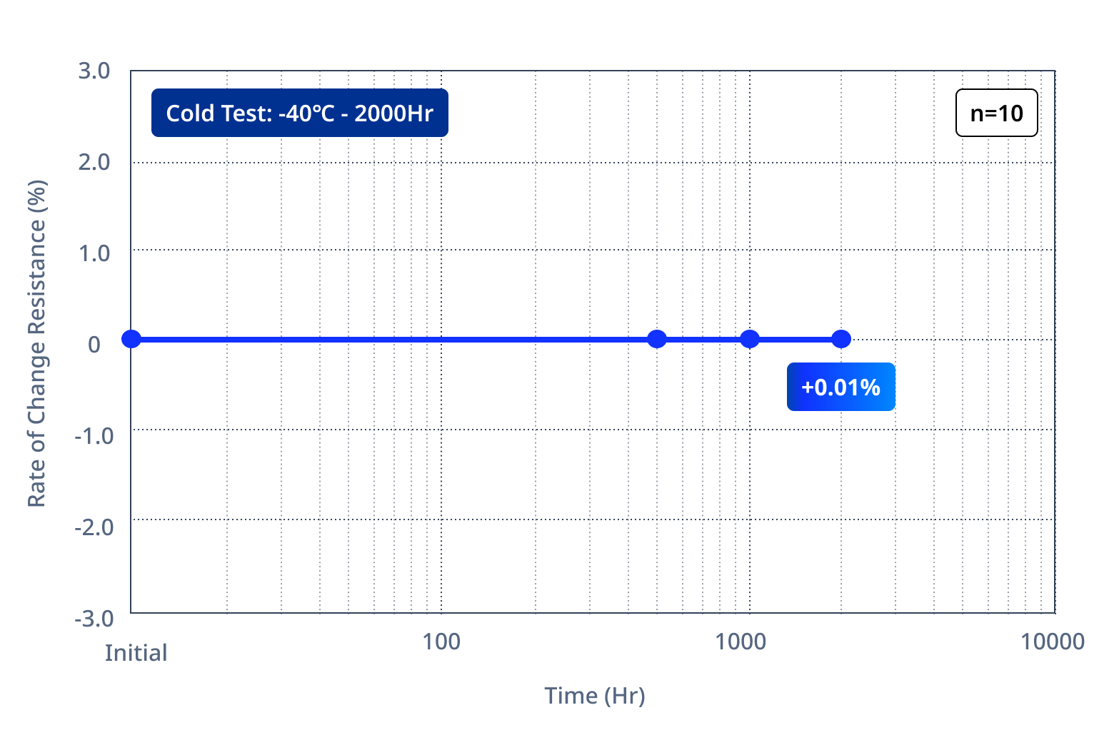
- Cold Test
:-40℃, 2000 hours
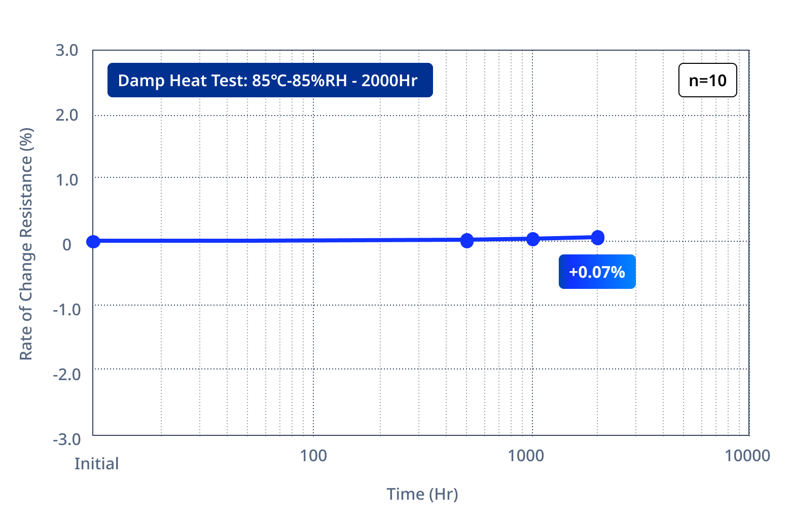
- Damp Heat Test
:85%RH at 85℃, 2000 hours
- Sulfidation Test
:H₂S 5ppm, 40±2℃ - 75±3%RH, 240hours
- Thermal Shock Test
: -40℃/30min-125℃/30min, 2000 hours
Frequently Asked Questions (FAQ) About Wire-Bondable NTC Thermistors
Q1. What is the difference between a wire-bondable NTC thermistor and a conventional chip NTC (SMD)?
A. Conventional chip NTC thermistors (SMD) are designed to be mounted on a substrate land using solder. In contrast, wire-bondable NTC thermistors are designed with Au electrodes for wire bonding on the top or bottom surface, allowing them to be connected directly through the wire-bonding process without depending on a substrate pattern. This enables flexible placement close to heat-generating components inside power modules.
Q2. What is AEC-Q200, and why is it essential for automotive designs?
A. AEC-Q200 is an automotive passive-component reliability standard established by the Automotive Electronics Council. It specifies tests such as high-temperature loading, temperature cycling, solder heat resistance, and vibration. In general, compliance with this standard is required for electronic components to be adopted by automotive component manufacturers. Because automotive applications have significantly higher safety and reliability requirements than consumer products, selecting AEC-Q200-compliant components is a basic principle of automotive design.
Q3. What types of designs require NTC thermistors with 200°C heat resistance?
A. They are increasingly required for EV and HEV inverters equipped with SiC power modules. SiC devices have a higher maximum junction temperature than silicon devices, and the operating temperature inside a power module can reach 175–200°C. Even in silicon-based designs, high-load operation and high-density packaging can create localized high-temperature conditions, so NTC thermistors rated for 175°C or higher may be selected.
Q4. Are there NTC thermistors compatible with the silver-sintering process in a formic-acid atmosphere?
A. Silver sintering is a high-reliability bonding technology that uses formic acid as a reducing agent. When selecting a compatible NTC thermistor, it is necessary to choose a product with a silver thick-film structure on the bottom electrode and resistance to the formic-acid environment. Compatibility varies by product, so please contact TDK for technical advice.
Summary
Wire-bondable NTC thermistors are key components that fundamentally improve temperature-sensing accuracy in SiC power modules for EV and HEV applications. Through wire-bonded mounting and optimized electrode designs, they overcome the challenge of placing temperature sensors close to heat-generating components in high-voltage environments—an issue that conventional SMD and MELF types cannot resolve.
Designers should confirm the following five points when selecting a product:
1. Maximum operating temperature — Products rated for 175–200°C are generally recommended for SiC inverters.
2. Chip size — Select a compact product suited to the limited space inside the power module.
3. Electrode structure — A top-side two-electrode design maximizes placement flexibility.
4. Assembly-process compatibility — Confirm compatibility with soldering, silver sintering, and wire-bonding processes.
TDK’s NTCWS series offers a variety of products, from compact chips measuring 0.31–0.48 mm square to products rated for operation at temperatures up to 200°C, providing solutions for a wide range of automotive power-module design requirements.

Optimize your power module’s thermal management with TDK’s compact, wire-bondable NTC thermistors rated for operation at temperatures up to 200°C. We can recommend products suited to your design specifications and provide technical support. Please feel free to contact us to request samples or make a technical inquiry.

Please click here for information on the list of distributors.
Related Links