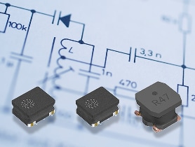
Power Inductor TFM Series

By using metallic magnetic materials with high saturation magnetic flux densities, these products have achieved the outstanding DC superimposition characteristics required of power inductors.
This article describes and explains in detail valuable information for our customers related to the products in the TFM series, including their structures, features, and applications.
What is the TFM series of small metal power inductors?
Figure 1 shows an overview of the TFM series. Starting with the TFM‑ALM series, we offer a lineup of additional series with further enhanced performance characteristics.
| Series | TFM-ALM | TFM-ALC | TFM-BLD | TFM-BLE | TFM-ALMA | TFM-BLEA | TFM-ALVA |
| Applications | Commercial Grade (Smart phones, tablets, other portable devices) | Automotive Grade (ADAS, ECU, in-vehicle cameras, radar, | |||||
| Product summary | Thin-film type inductors using metallic magnetic materials. | ||||||
| Improved over earlier products by optimizing internal pattern. | Further enhanced over the ALM series by changing metals and optimizing internal patterns. | L-shaped terminals enable narrower pitch mounting than five-surface electrodes. | Magnetic materials and structure achieve lower resistance and higher current than the BLD series. | Compliant with in-vehicle quality standards; rated for 150°C. | Improved magnetic materials and design lower resistance and boost high-current capability compared to the ALMA series. | Improved metal materials enhance voltage-withstand performance over the ALMA series. | |
| Features | ・Improved DC resistance and DC superimposition over earlier products. | ・Low-loss coil | ・L-shaped electrode | ・Low resistance ・High current ・L-shaped electrode | ・AEC-Q200
| ・AEC‑Q200 compliant ・Low stray magnetic flux ・Rated voltage: 20 V (guaranteed) ・Low DC resistance ・High current‑handling capability ・L‑shaped electrode | ・AEC‑Q200 compliant ・Low stray magnetic flux ・Rated voltage: 40 V (guaranteed; usable in battery lines) |
Structure of the TFM series that achieves a compact form while delivering industry‑leading performance
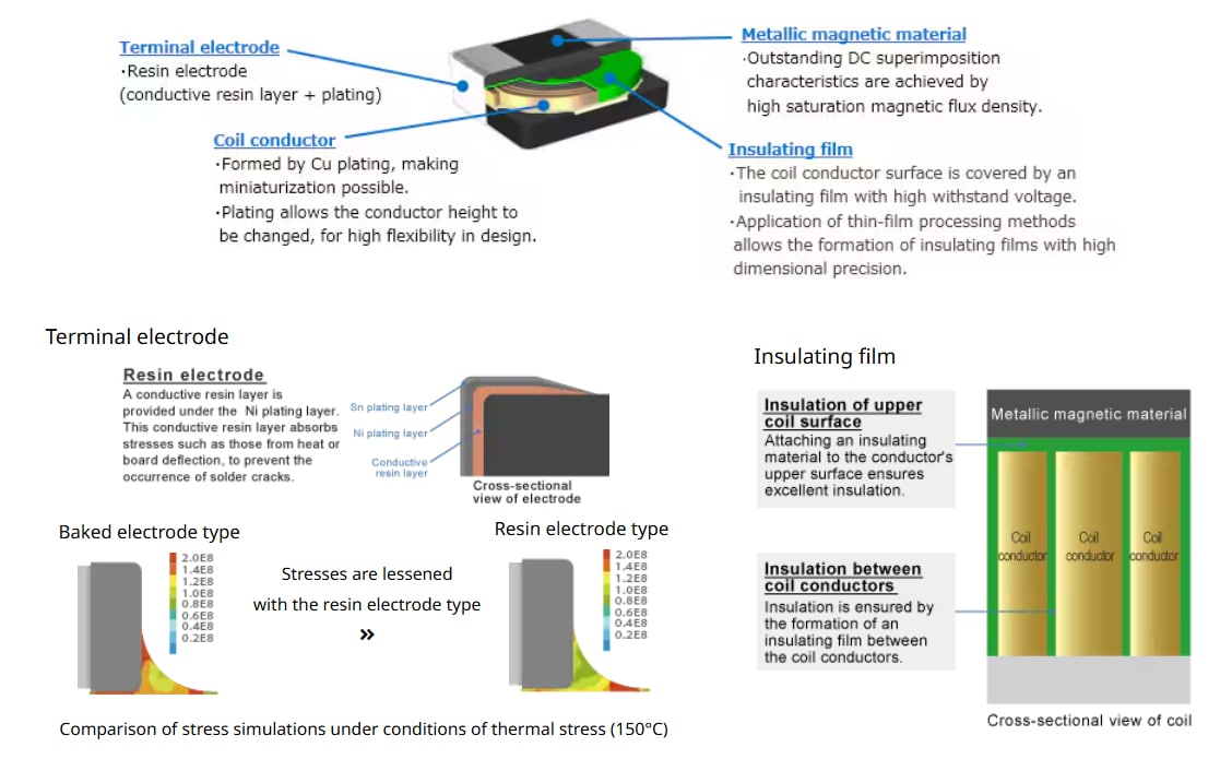
The TFM series inductors are designed and produced utilizing TDK's thin-film processing.
The coils are formed by Cu plating, enabling support for highly flexible designs, and the use of resin in terminal electrodes helps in reducing the potential stress caused by heat and board flexing.
With proprietary material technology and structural design, the TFM series features a wide and diverse product lineup
The features of each TFM series are shown in Figure 3. The TFM-ALMA, BLEA, and ALVA series are automotive-grade products capable of withstanding temperatures up to 150°C.
Series | TFM-ALM | TFM-ALC | TFM-BLD | TFM-BLE | TFM-ALMA | TFM-BLEA | TFM-ALVA |
Appearance | |||||||
Operating | -40 – 125°C | -55 – 150°C | |||||
Magnetic | Metallic magnetic material | ||||||
Terminal | Resin electrode (conductive resin layer + plating) | ||||||
Features | |||||||
・Standard | ・High | ・L-shaped electrode | ・Low resistance | ・Automotive | ・Automotive | ・Automotive specifications | |
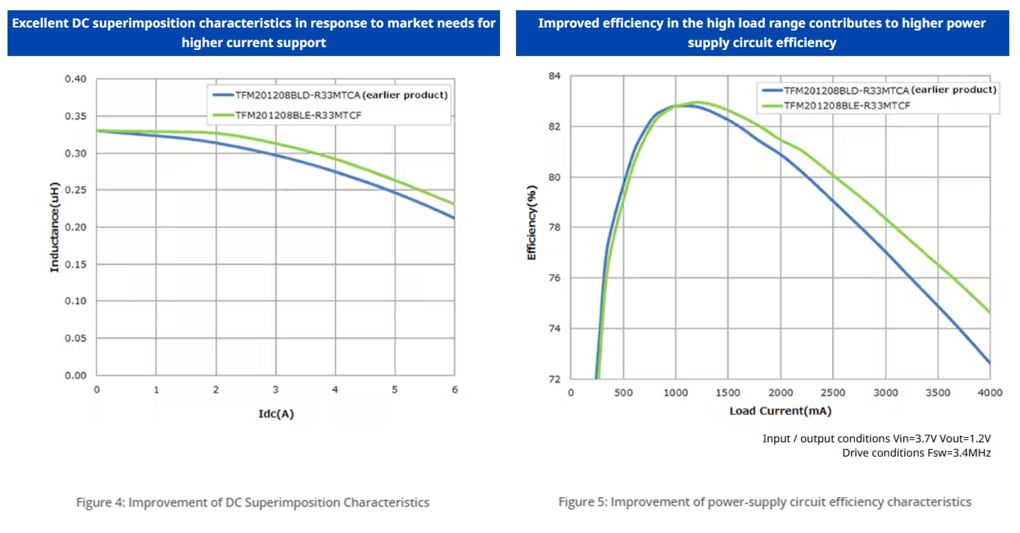
In the TFM series for consumer applications, there is a wide lineup ranging from high-current types that improve DC superposition characteristics and are effective for enhancing power supply efficiency in high-load regions, to low core-loss types that are effective for improving power supply efficiency in light-load regions.
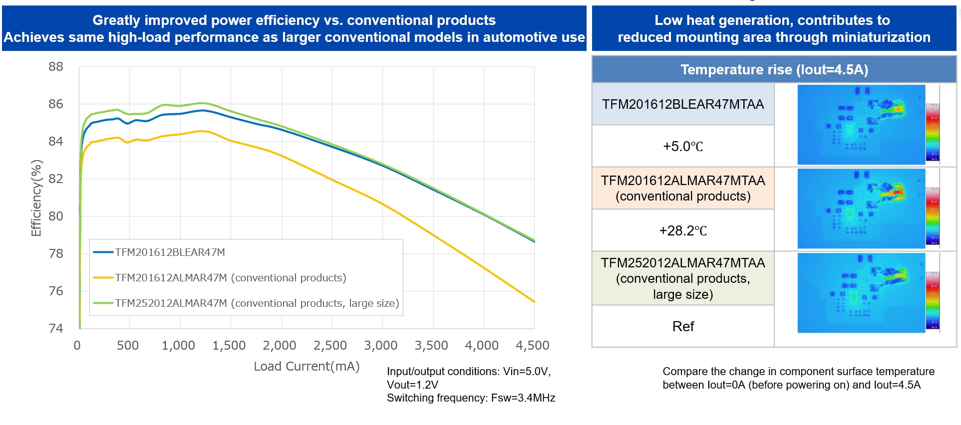
The newly added TFM-BLEA series for automotive applications achieves lower resistance and higher current capability compared to the conventional ALMA series, significantly improving power supply efficiency in high-load regions, which is crucial in automotive environments. Additionally, the temperature rise characteristics when current flows through the inductor are better than those of previous products, resulting in less heat generation and enabling a reduction in mounting area by replacing with more compact shapes.
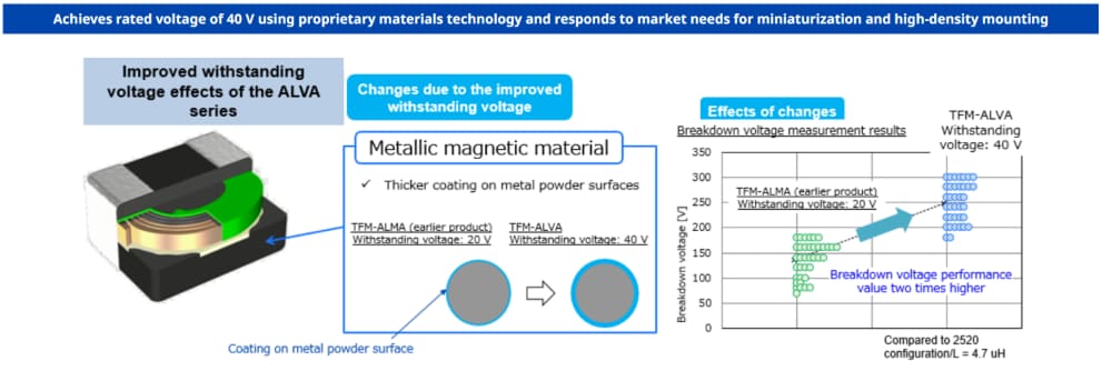
The TFM-ALVA series has been added to the lineup for automotive-grade products, which has been possible through the development of new metallic magnetic materials.
This makes this series suitable for battery lines that were previously difficult to support with compact power inductors.
Applications of the TFM series
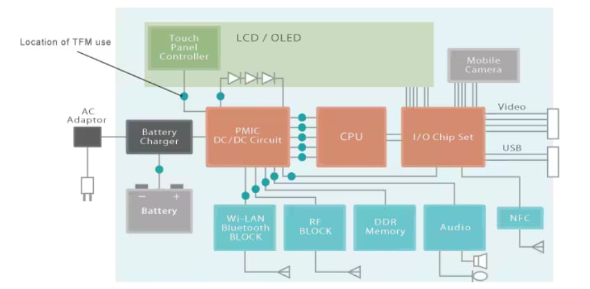
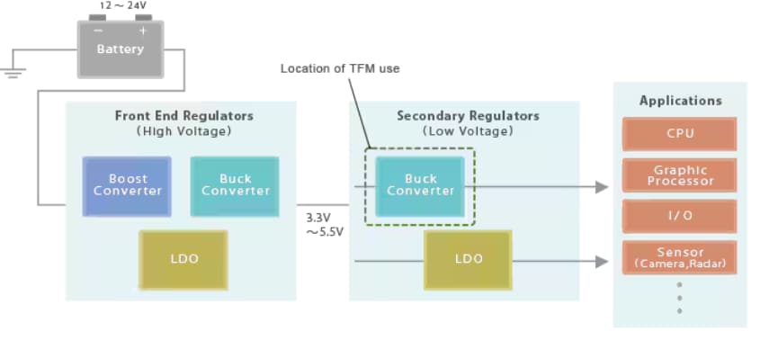
Example applications which use the TFM series are shown in Figure 8. Due to their compact size, and large current ratings they are ideal for applications requiring high-density mounting such as smartphones and automotive ECUs.
Application | Block diagram |
Smartphone | |
Automotive ECU |
TFM series product lineup
A list of products by series and shape is shown in Figure 8. Detailed information can be viewed and samples can be purchased by clicking on the product type name.
| Applications | Commercial Grade | Automotive Grade | ||||||
Size | Height | TFM-ALM | TFM-ALC | TFM-BLD | TFM-BLE | TFM-ALMA | TFM-BLEA | TFM-ALVA |
1.4×1.2 | 0.65 Max. | |||||||
0.8 Max. |
|
|
|
|
| |||
1.6×0.8 | 0.8 Max. |
|
|
| ||||
2.0×1.2 | 0.8 Max. |
|
|
| ||||
1.0 Max. |
|
|
|
|
| |||
2.0×1.6 | 1.0 Max. |
|
| |||||
1.2 Max. |
|
|
| |||||
2.5×2.0 | 1.2 Max. |
|
|
|
| |||
3.2×2.5 | 1.2 Max. |
|
|
|
| |||
What is a power inductor?
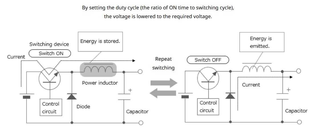
A power inductor is an inductor used in power circuits such as DC-DC converters, and is sometimes called a power coil or a power choke. Inductors have the property of storing energy through self-induction, and DC-DC converters, such as chopper-type converters, use a combination of this inductor and switching elements to convert voltage. (Refer to Figure 10).
Inductors are classified into multilayer, thin-film, and wire-wound types according to their construction methods. The wire-wound type, which can carry large currents, is the mainstream for power inductors This type can be integrated with a variety of products that have either ferrite or soft magnetic metal cores. In recent years, smaller and thinner multilayer and thin-film types are also becoming capable of handling large currents.

