Noise Countermeasures and Audio Quality Improvement for Bluetooth Audio Devices

The recent mass implementation of True Wireless Stereo (TWS) within earbuds, with their comfortable cable-free non-tangling fit, has yielded vastly improved sound quality over traditional Bluetooth audio technology. TWS also comes with the ability to cancel external noise (isolation) which results in quieter playback. This feature allows users to use TWS-based devices without concerns of the sound being “broadcasted” to surrounding areas.
Additionally, Bluetooth connected speakers, which also do not require cables for signal transmission, allow for unfettered placement of playback devices and speakers. These mobile speakers, with their built-in amplifiers, can operate on battery power and be completely portable.
Bluetooth enabled audio devices are easy to use, easy to connect to and have many advantages. However, since they require a wireless signal, they can be susceptible to problems that do not occur with cable-connected audio devices.
This article describes phenomena that can cause problems within Bluetooth audio designs and will provide examples of potential countermeasures.
Contents
- RF signals and effects on operation
- Noise problems in speaker lines
- Noise countermeasures for speaker lines
- Noise problems on microphones lines
- Noise countermeasures for microphone lines
- Implementing noise countermeasures that do not degrade sound quality
- Degradation of communication quality (occurrence of communication errors) for TWS earbuds
- Countermeasures against degradation of receiving sensitivity by using noise suppression
- Improvement results of receiving sensitivity degradation in speaker lines
- Recommended products for noise suppression and ESD countermeasures protection
- Conclusion
RF signals and effects on operation
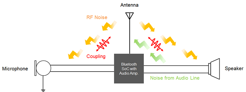
In devices free of wired connections by use of wireless connections, the quality of the RF connection (receiving sensitivity) determines the ability to transmit and receive data which then impacts both operation and battery life. In applications that have RF functionality incorporated into physically small wireless devices (e.g. earbuds), the printed circuit board (or PCB) with its copper traces and/or wired interconnections for each audio input and output are in close proximity to the antenna used for RF transmission and reception. RF signals emitted by the antenna can become potential EMI noise and degrade the audio quality when transposed unto the microphone and/or speaker audio lines.
The connection methodology to the antenna is important as it is susceptible to noise due to the proximity of the speaker and microphone lines. Digital amplifiers, which are typically used in battery powered portable audio devices, can radiate the harmonic noise caused by the switching process. These harmonics can interfere with the RF signals which are the output/input to and from the antenna. Due to this close proximity, coupling occurs between the antenna and the wiring, and the problem of low receiving sensitivity by the antenna becomes problematic.
All of these potential EMI noise sources are shown in Figure 1.
Noise problems in speaker lines
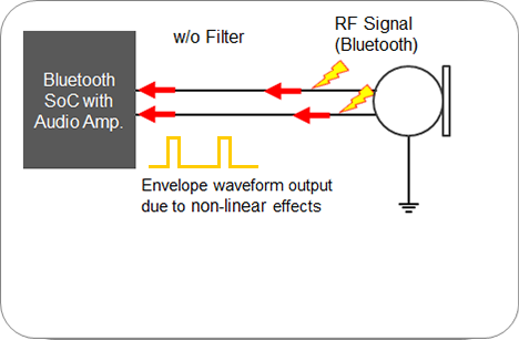
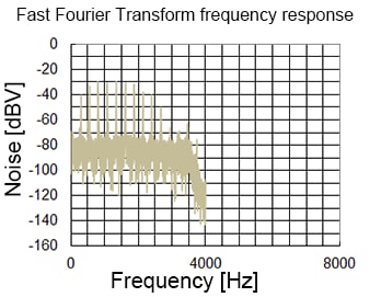
In the case of Bluetooth Classic Audio (versus BLE audio), communication between devices is performed at regular intervals and when the RF signal is inputted into the audio amplifier, an envelope waveform is generated due to non-linear effects. Since the frequency of this envelope waveform is in the audible range, it is also outputted to the speakers along with the desired signal and can be heard as audible noise. This RF radio envelope waveform problem is not unique to Bluetooth applications, as it also occurs within cellular systems and Wi-Fi technologies.
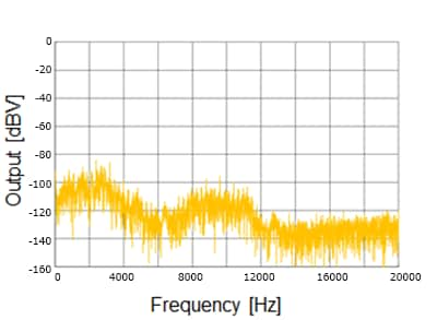
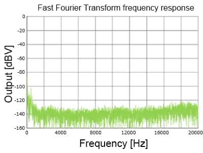
Figure 2-(a) shows standard wired connections between the output of the Bluetooth SoC and the speaker. In this example, the wired connections pick up the RF signal and transmit this unwanted noise into the SoC. Figure 2-(b) shows the Fast Fourier Transform (FFT) of the output to the speaker displaying the envelope waveform and in Figure 2-(c) shows this envelope noise in the time domain.
Noise countermeasures for speaker lines
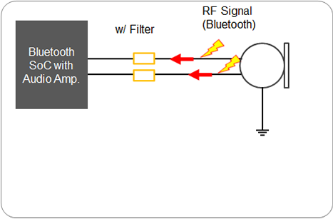
The audible noise created by the RF envelope waveform needs to be filtered out and/or attenuated prior to being inputted to the speaker. The same is true for any RF signal that the speaker’s wired connections pick up from the RF antenna circuit. The primary countermeasure is to attenuate the Bluetooth RF signal (2.4 GHZ band) that causes the envelop waveform.
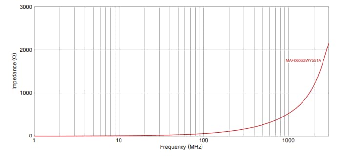
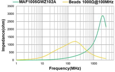
This can be performed by careful analysis and a good understanding of small passive filters. One such filter candidate is TDK’s MAF series noise suppression filters. The impedance (/Z/) versus frequency response is shown in Figure 3.
Also, because TWS earbuds come into physical contact with the user’s hands when being used, electrostatic discharge (ESD) protection is also necessary for the wiring that connects to both the microphone and the speaker since both have a non-protected inherent path from the acoustic connection to the outside world. For this potential problem,
TDK has developed a notch filter (AVRF series) with built-in ESD protection functionality to provide both RF noise reduction and ESD countermeasures for the audio signal lines.
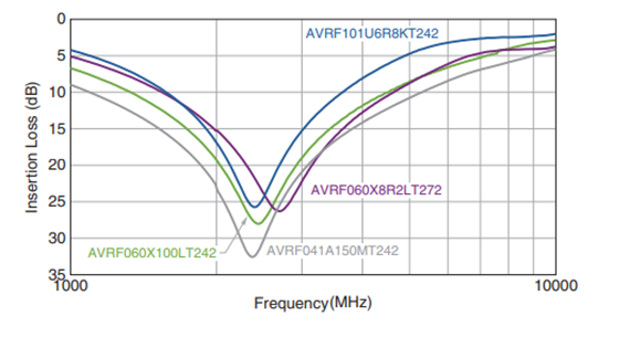
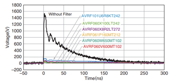
Figure 4 shows the performance of various AVRF notch filters for insertion loss versus frequency (left) and the discharge voltage waveform versus time (right).
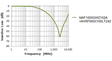
Figure 5 shows the insertion loss characteristics when an MAF series noise suppression filter (with its series inductor) is combined with an AVRF series notch filter with its ESD protection (and with its series capacitor) to create a resultant low-pass output filter. This configuration yields high attenuation characteristics in the 2.4 GHz band and blocks respective noise from entering the Audio amplifier, and thus no unwanted noise is regenerated via the envelope waveform.
Noise problems on microphones lines
When a Bluetooth RF signal is transposed onto the microphone lines, an envelope waveform is also formed and synthesized into an input signal from the microphone to the input of the audio processor in the same manner as on a speaker line. Once this added noise gets into the audio processor, it is then outputted as undesired audible noise on the speaker side. This scenario can cause malfunctions within noise reduction microphones.
Figure 6 shows, on the left side image, how the RF Bluetooth signal can get transposed unto the wired connections within the microphone circuit. This unwanted noise can then get into the Bluetooth SoC. As the desired signal is processed, the noise gets added and the two signals are sent out coupled together. Like for the speaker circuit, the coupled signal generates undesired audible noise as shown in the FFT noise versus frequency plot on the upper-right and in the distortion level (D) versus time plot on the bottom-right.
Noise countermeasures for microphone lines
Figure 7 shows the results when comparing: 1) an added MAF noise suppression filter, 2) an added general ferrite chip bead only, and 3) with no filtering added as the noise suppression components on a microphone line. Chip beads have insufficient impedance and corresponding noise attenuation in the 2.4 GHz band. But by implementing the aforementioned MAF filter, noise attenuation is increased, and output noise level is decreased to an undetectable level in audible frequencies.
Implementing noise countermeasures that do not degrade sound quality
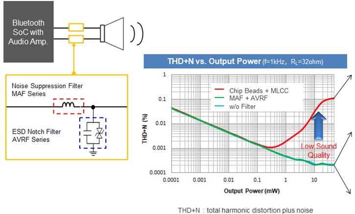
Ferrite chip beads and multilayer ceramic capacitors (MLCCs) have been historically used for conventional low-cost noise suppression solutions. These passive components both have non-linear characteristic behaviors depending on the current and voltage, and as a result, when these products are inserted into an audio line circuit, harmonic distortion can be generated and outputted from the speakers when the audio amplifier output [volume] is increased. The audible impact from this is a sound with enhanced treble due to the addition of distortion noise.
Figure 8 shows the signal output of the audio amplifier to the speaker when using an audio analyzer to measure the total harmonic distortion plus noise (THD+N) characteristics with and without noise suppression components being added. When ferrite chip beads and multilayer capacitors are used in tandem, THD+N increases significantly, at some frequency, as the amplifier output increases. This is shown by the red line in the center graph. There is a trade-off between the effectiveness of this countermeasure solution and the audio quality, and a decrease in sound quality may be unavoidable as a result of the noise countermeasures being used.
On the other hand, there is no increase in either THD+N with the MAF+AVRF solution or when no noise suppression components are implemented, though the latter does not remove any noise that is on the speaker lines. The THD+N measurement results indicate that neither the MAF or the AVRF components cause non-linear changes due to the voltage or current in their respective operational ranges used by the speaker, and therefore, harmonic distortion does not occur. From a signal distortion point of view, the MAF+AVRF solution mimics the “no filter” performance. This is shown by the green and blue lines in the center graph of Figure 10.
Note: For audio characteristics, the lower the THD+N value, the better the sound quality
Degradation of communication quality (occurrence of communication errors) for TWS earbuds
In True Wireless Stereo (TWS) earbuds, the speaker unit is always hard wired to the PCB, and this wired connection can lead to coupling with the antenna and therefore must be considered. Also, when speakers are driven by digital amplifiers using a switching method, higher frequency harmonic noise associated with the fundamental switching frequency can be radiated from the speaker line. This radiated noise is very weak, but it still can interfere with a weak Bluetooth RF signal, as the distance to the antenna is very short, usually within 20 mm, and can be a source of degradation of sensitivity. Verifying this phenomenon can be challenging at times to confirm.
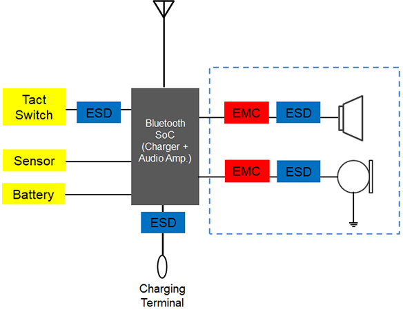
If the Bluetooth communication distance between devices is large and/or there are RF signal path obstructions, the radio wave signals received by the antenna will be weaker. If there is noise interference in the RF band, the receiving sensitivity of the TWS earbuds can fall below the requirement of the antenna, causing data errors and interruptions in operation. These weak signals also may make it problematic for the two devices to confirm each other's presence, resulting in a disruption of the wireless connection. Figure 9 shows a simplistic block diagram of TWS earbuds.
Countermeasures against degradation of receiving sensitivity by using noise suppression components
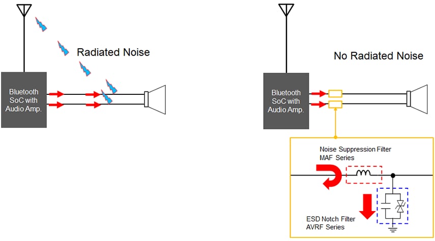
What measures can be effective in preventing radiated noise from the speaker lines and wired connections from coupling with the antenna to reduce degradation of receiving sensitivity? Some of the ways to reduce coupling effects are to shield the wires, route the connection wires away from the antenna or put the antenna in a location that is not as susceptible to coupling.
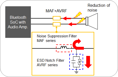
To counter harmonic noise from amplifiers, circuits with inductor and capacitor components can be used to eliminate noise radiation in the Bluetooth 2.4 GHz band by reflecting the noise [via an inductor] and bypassing it [with a capacitor] to ground. In addition, the implementation of noise suppression components has the ability of reducing unwanted noise from coupling with the antenna, which improves receiving sensitivity. Figure 10 highlights and pictorially explains this approach.
Improvement results of receiving sensitivity degradation in speaker lines
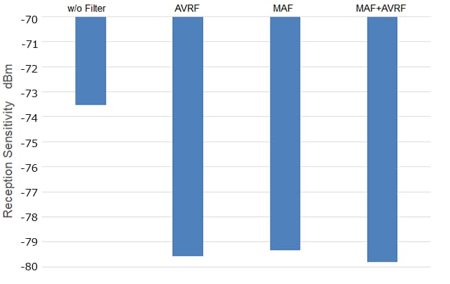
Figure 11 shows the result of the receiving sensitivity of the TWS earbuds when the RF output on the transmitter was turned down and the playback sound started to break up while music was played with a Bluetooth Audio signal transmitter and TWS earbuds. Audio interruption did not occur up to the weak reception conditions when noise suppression components were inserted into the speaker line, indicating that noise interfering with the antenna was reduced.
Insertion of MAF, AVRF, and MAF+AVRF countermeasures, which have noise attenuation effects in the Bluetooth 2.4 GHz band, resulted in approximately 6 dB of improvement in receiving sensitivity.
Recommended products for noise suppression and ESD countermeasures protection
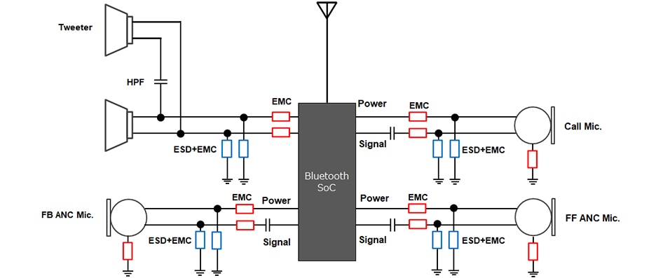
Figure 12 shows an example of the latest TWS earbuds audio circuit. As one can see, there are numerous electromagnetic compatibility (EMC) and ESD components that are used on the audio lines for high sound quality and noise cancellation performance.
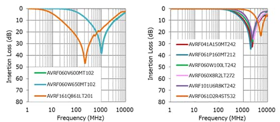
Figure 13. shows the lineup of the MAF series of noise suppression filters for audio lines, and their respective frequency characteristics with only MAF filters (left) and with AVRF notch filters (right).
It is important to note that each specific product and/or design may have noise sources at different frequencies. The designer needs to select and use products that are effective at the frequencies for which noise suppression is needed. As shown in Figure 13, using the MAF filter alone will produce some improved level of noise reduction, but greater attenuation can be achieved by using the two filters in tandem with the AVRF notch filters also adding ESD protection.
| Size mm [inch] |
ITEM | Impedance [Ω] @900MHz Typ. |
DC Resistance [Ω] |
Rated Current [A] |
Corresponding frequency domain | ||||
|---|---|---|---|---|---|---|---|---|---|
| Typ. | Max. | Max. | Cellular Band | WiFi, Bluetooth 2.4GHz |
WiFi 5GHz |
||||
| 700MHz- 1GHz |
1.5GHz- 2.7GHz |
||||||||
| 0603 [0201] |
MAF0603GWY551A | 550 | 1.70 | 2.20 | 0.125 | ✔ | ✔ | ||
| MAF0603FAL330B | 250 | 0.37 | 0.70 | 0.2 | ✔ | ✔ | |||
| MAF0603FAL470B | 390 | 0.42 | 0.70 | 0.2 | ✔ | ✔ | |||
| 1005 [0402] |
MAF1005GAD152A | 1500 | 0.55 | 0.70 | 0.40 | ✔ | ✔ | ✔ | |
| MAF1005GAD262A | 2600 | 1.00 | 1.20 | 0.30 | ✔ | ✔ | ✔ | ||
| MAF1005GWZ102A | 1000 | 1.3 | 1.6 | 0.15 | ✔ | ✔ | |||
Frequency responses of MAF filters and MAF+AVRF combined filters
Figure 14 shows the lineup of the AVRF series of notch filters with ESD protection functions, and the frequency response curves of the AVRF series in terms of insertion loss.
| Size mm [inch] |
ITEM | Rated Voltage Vdc [V] MAX. |
Capacitance C (1MHz) [pF] |
Break Down Voltage Vbr [V] |
Insertion Loss [dB] |
Corresponding frequency domain | ||||
|---|---|---|---|---|---|---|---|---|---|---|
| Cellular Band | WiFi Bluetooth 2.4GHz |
WiFi 5GHz |
D-Amp Noise |
|||||||
| 700MHz- 1GHz |
1.5GHz- 2.7GHz |
|||||||||
| 0402 [01005] |
AVRF041A150MT242 | 10 | 15 | 16 | 20min. (2.4GHz) |
✔ | ✔ | |||
| 0603 [0201] |
AVRF060V600MT102 | 3.5 | 60 | 6.8 | 20min. (1GHz) |
✔ | ||||
| AVRF060W650MT102 | 5.5 | 65 | 8 | 20min. (1GHz) |
✔ | |||||
| AVRF061P160MT212 | 12 | 16 | 20 | 20min. (2.1GHz) |
✔ | ✔ | ||||
| AVRF060X100LT242 | 7 | 10 | 12.8 | 20min. (2.4GHz) |
✔ | ✔ | ||||
| AVRF060X8R2LT272 | 7 | 8.2 | 12.8 | 20min. (2.7GHz) |
✔ | ✔ | ||||
| AVRF061D2R4ST532 | 20 | 2.4 | 43 | 15min. (5.3GHz) |
✔ | |||||
| 1005 [0402] |
AVRF101U6R8KT242 | 28 | 6.8 | 39 | 20min. (2.4GHz) |
✔ | ✔ | |||
| 1608 [0603] |
AVRF161Q861LT201 | 19 | 860 | 27 | 20min (200MHz) |
✔ | ✔ | |||
AVRF series insertion loss (dB) versus frequency
Conclusion
Applications like TWS have many challenges besides trying to make everything fit into a limited sized package. With the required compactness, the likelihood of the various electrical circuits impacting each other becomes a challenge unto itself. Of particular concern is the antenna’s RF signal “noise” being transposed onto either the speaker connection lines and/or the microphone lines or one of them generating noise that gets coupled on the RF antenna circuit.
It was shown that TDK has developed, tested, and is now producing specific passive component solutions that not only filter/attenuate undesired audible noise sources, but ones that themselves add very little distortion to the desired signals. The components addressed in this paper were the MAF series noise suppression filter and the AVRF series notch filter. The AVRF notch filter also provides an additional function as it adds a very high level of ESD protection.

